Only one half of my keyboard works at a time
The keyboard won't send output
Steps to follow when your keyboard does power on, but won't provide output.
My keyboard layout is mirrored
Steps to follow when the left half acts as the right, and the other way around.
When to use
You should use this document when you're using and/or experiencing the following.
Products
This page applies to the following products:
- Any wired split keyboard being sold at splitkb.com.
Situations
Use this page when:
- The keyboard half you're connecting does turn on, but the other half does not.
- The keyboard half you're connecting does turn on, the other half seems to turn on as well, but does not provide output when you press its keys.
Expected outcome
After following the instructions on this page:
- Both of the keyboard halves will turn on and provide output as expected.
When to avoid
Do not use this page when:
- You are using a wireless controller.
You've connected your keyboard to your host device, and find that only the half that's directly connected to your device works. The other half won't turn on, or maybe the LEDs will light up, but it won't give output.
If the other half won't turn on, then it's likely an issue where the other half is unable to receive power. If the other half does turn on but won't provide output, it's likely an issue with transmitting data. Let's get started!
Check the interconnect cable
The cable used to connect both sides of the keyboard to one another can cause issues.
USB C cable
For kits using a USB C cable to connect both halves, verify whether the cable is capable of transmitting data. Some USB C cables only transmit power. Please try another cable, or use the cable to connect the keyboard to the host device instead (using the keyboard's other USB port). If the cable is capable of transmitting data, then the connected keyboard half should provide output when typing on it.
All Halcyon Series keyboards use a USB C cable to connect both halves.
TRS or TRRS cable
For kits using either a TRS or TRRS cable for the interconnect, check the following:
- Is the cable fully plugged in? There's not much force needed to plug in a TRS or TRRS cable, but you shouldn't be able to press the cable into its jack any further. Try to firmly press on it to ensure it sits snug into the jack.
- Is the cable correctly wired? It's very rare, but a cable can be defective. If you happen to own a multimeter, you can poke at the matching rings on both sides to see if the cable is connected properly on the inside. The tip should have continuity with the tip, the sleeve with the sleeve, and any rings should have continuity with its matching ring on the other side of the cable.
If the cable is indeed plugged in and wired correctly, it could be a soldering issue.
All Aurora Series kits can use either a TRS or a TRRS cable. The Kyria from rev2.0 up to rev3.1 can use either a TRS or TRRS cable as well.
TRRS cable
For kits using a TRRS cable, check whether the cable is indeed a TRRS cable. This is the case for the Elora rev 1, Kyria kits from revision 0.7 up to 1.4, and most kits not sold at splitkb.com.
A TRRS cable has connectors which are 3.5mm in diameter, and have four shiny conductive parts: the tip, two rings and the sleeve, separated by three black rings in total. Those conductive shiny parts should have equal widths, too, where a TRS cable instead has a tip that's twice as large as the ring and the sleeve.
Soldering
If the cable isn't the problem, then perhaps it's the soldering on the connector.
Have a look at both the microcontrollers and the TRRS connectors you've soldered, and read through the Soldering healthy joints page. A so-called "cold joint" can prevent your keyboard from making a reliable connection. Usually, touching it up with a hot iron and potentially a little extra solder can go a long way.
Often, the cause of only one half working has to do with continuity: the ability for electricity to flow between two points. You'll want to make sure there is continuity between the right points, to ensure you have no solder bridges or defective components. To check for continuity, you can use a multimeter that has a continuity check mode. Often, the multimeter can emit a tone so you can hear it when there's a connection between two points.
Check for continuity on the following pins, while not having the halves connected to one another:
- Each pin of the TRRS jack should connect with its corresponding pin on the other half of the keyboard. Next to that, each pin shouldn't be connected to any other pin on the same TRRS jack.
- The pins on the TRRS jack should connect with the appropriate pins on the microcontroller. You can refer to the schematics, for example the Aurora Series schematics and the Kyria schematics.
If you've used them, also check the orientation of your RGB underglow LEDs and per-key RGB LEDs. If they are oriented the wrong way, they will cause an electrical short which causes your keyboard to not work. If you find you have oriented an LED incorrectly, you'll need to desolder it.
Controllers
If your keyboard is using a different controller on each side, they may not be compatible. Of particular note:
- Do not mix and match various controller types. A wireless controller will not be compatible with a wired controller, and an RP2040-based controller will not be compatible with an ATmega-based controller.
- When using a Liatris with another RP2040 controller, be sure to solder the VCC jumper to the 3.6V setting. Usually, RP2040 boards aren't built to accept a higher voltage on their VCC pin.
In general, it's best to use the same controller for both sides: it's the most predictable.
Pro Micro
One of the ways QMK can detect which side should act as the main side of a split keyboard is by means of reading the voltage on the VBUS pin of the microcontroller. Though rarer these days, if you're using an original Pro Micro, it may come with a J1 jumper, which bypasses the voltage regulator. In turn, this causes the controller to think it's receiving power directly from the host device, instead of through another controller.
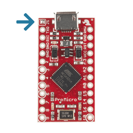
A SparkFun Pro Micro with its J1 jumper presoldered.
If that's the case for your controller, decide which half you want to always connect to the host device first (the main half). Then, desolder the J1 jumper on the half you won't connect directly to the host device (the peripheral half).
Firmware
The firmware on both sides needs to match for them to understand one another. Be sure to flash the same firmware file to both halves, unless you're deliberately compiling separate firmware files for each half. Also see: When do I need to flash my microcontroller?
If it still won't work, it can help to reset your controller's EEPROM on both halves. You can then reflash your firmware to both halves and verify whether it now works. Clearing the EEPROM can help to solve issues to do with the settings your keyboard keeps between restarts.
The keyboard won't send output
Steps to follow when your keyboard does power on, but won't provide output.
My keyboard layout is mirrored
Steps to follow when the left half acts as the right, and the other way around.