Resistors
You should perform this step if you chose the OLED displays or wish to use other I2C-enabled accessories, either right away or possibly in the future. If not, you can go to the next step using the button below.
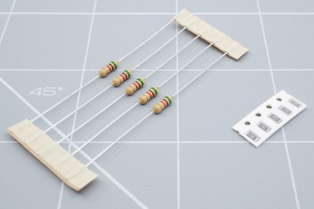
A set of through hole and SMD resistors.
Your kit will contain two pairs of either through-hole or SMD resistors. The keyboard exposes an I2C bus which is most commonly used to communicate with an OLED. To work properly, the I2C bus requires the installation of these pull-up resistors.
Although this step is optional if you are not using I2C devices like OLEDs, installing them anyways won't hurt and prevents you from losing them in case you need them in the future.
Through-hole resistors
If you’re using SMD resistors, please skip to the SMD resistors section on this page.
Check which side is recommended for your kit by looking for a white resistor outline next to the resistor pads. They’ll be marked R1 and R2. On most kits this will be the top side. Only the Aurora Helix will have an R3 too.
On most kits they will physically fit on the other side too, but we don't recommend it. If you do go for this approach, make sure to double-check the clearance - especially when using a JST jack for a wireless controller.
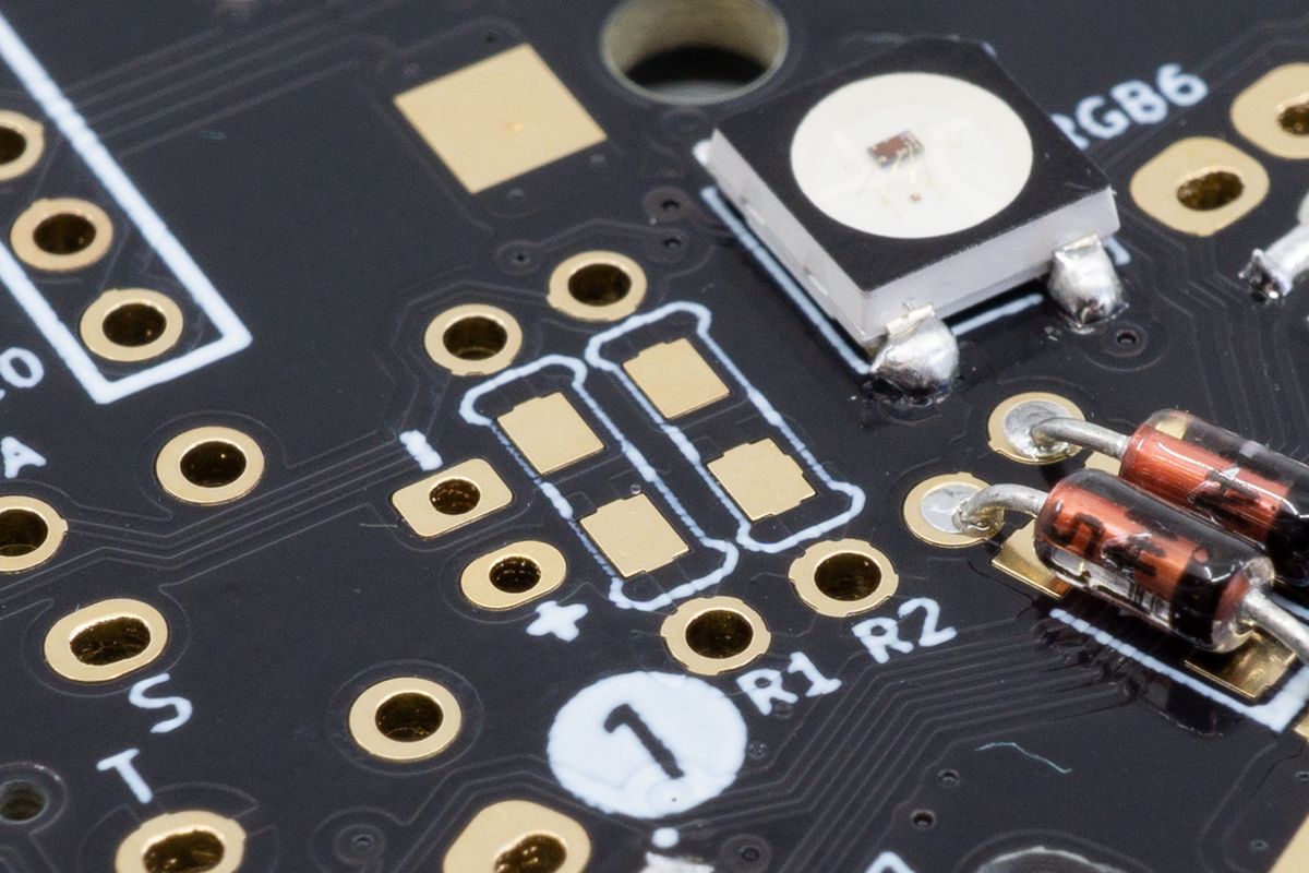
The resistor footprints on the PCB, marked R1 and R2 here.
Similar to the diodes, bend the resistors and insert them into the PCB. Unlike diodes, their orientation does not matter.
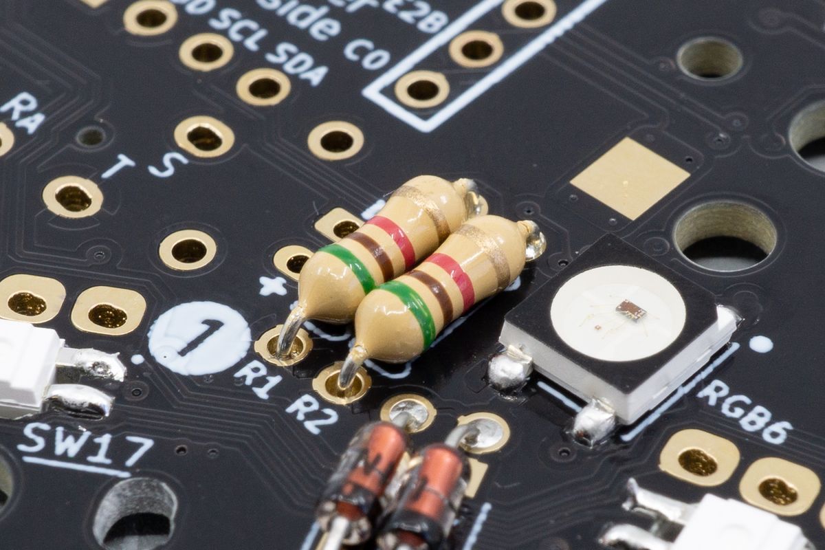
Two through-hole resistors inserted into their footprints.
Bend the legs a little after inserting them so they’ll stay in place.
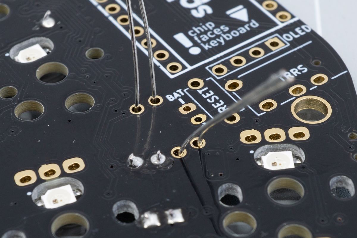
The leads sticking out the other side of the PCB. Note that there's no white outline on this side.
Solder them from either the top or the bottom. On the Aurora Sweep specifically, we recommend soldering them from the bottom so you can trim the leads off flushly at the top side.
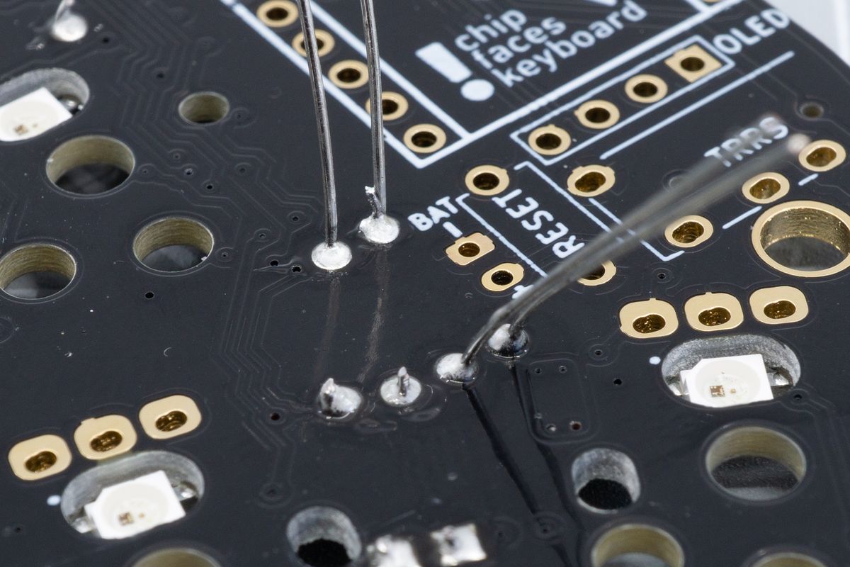
Soldered joints of the resistors, with their leads still attached.
Cut the legs off flush using a flush cutter. You won’t need to save these legs for a later step.
Remember, use one hand to hold the leg and the other to cut it - you don't want loose legs flying everywhere.
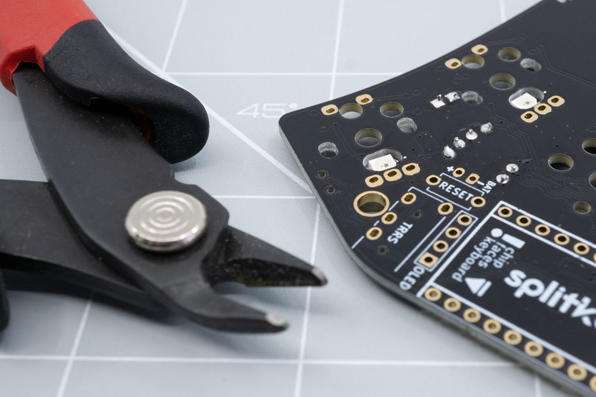
A flush cutter tool peeking at the freshly clipped joints.
SMD resistors
If you’re using through-hole resistors, please go back to the through-hole resistors section on this page.
Check where they need to be installed for your kit by looking for a white resistor outline next to the resistor pads. They’ll be marked R1 and R2. On most kits this will be the top side. Only the Aurora Helix will have an R3 too.

The resistor footprints on the PCB, marked R1 and R2 here.
Similar to the diodes, solder some tin on one of the two rectangular pads on the resistor footprint. Leave the pads with holes alone - you won’t need them for SMD resistors.
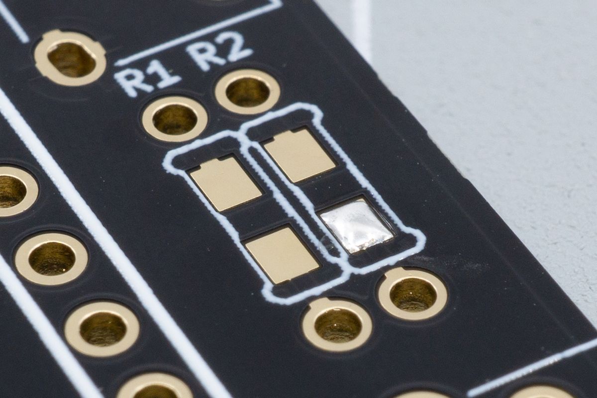
One of the resistor's SMD pads soldered, to make the next step easier.
Grab a resistor using tweezers in one hand, and use your soldering iron with your other hand. Move the resistor next to a pad you just soldered, and heat up the solder until it melts.
Then, move the resistor in place, touching both the resistor terminal and the pad with your soldering iron until you notice a solder joint form — this usually only takes a second or two.
Remove the soldering iron, wait until the solder joint solidifies, and release the tweezers.
Unlike diodes, their orientation does not matter.
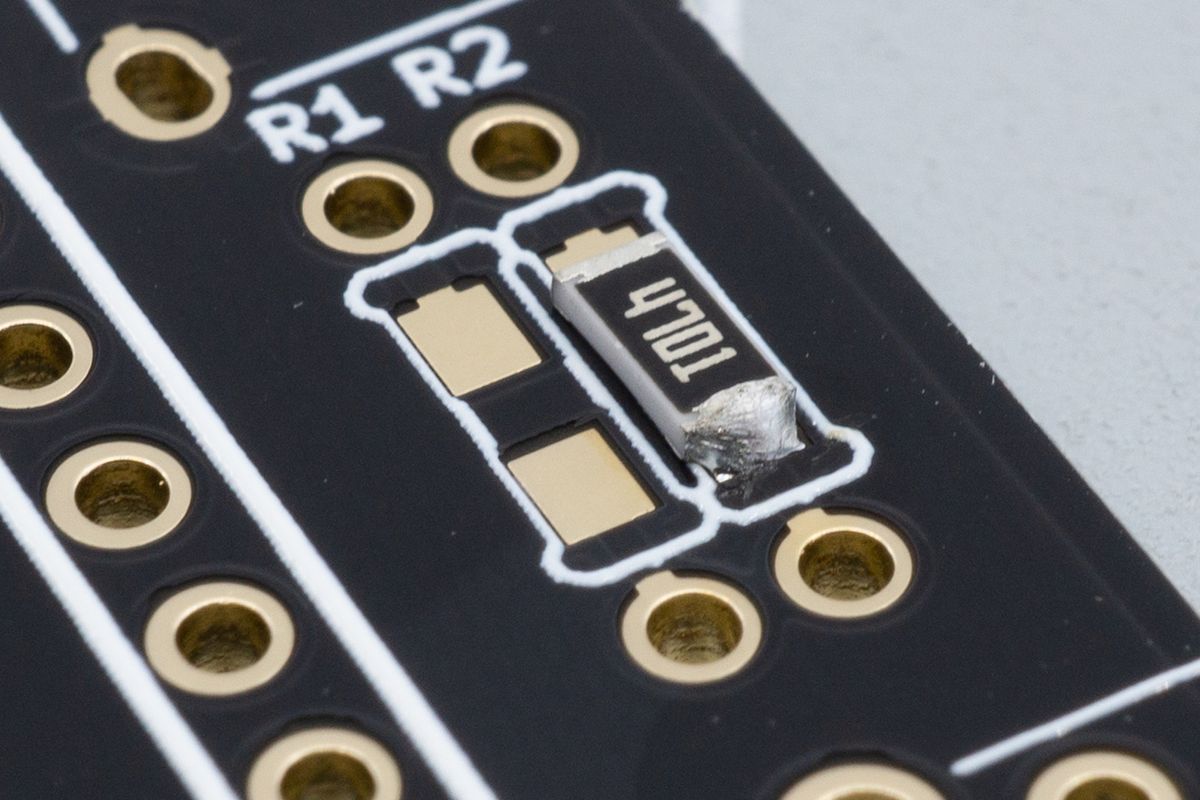
A resistor's first soldered joint. You can still adjust its position easily by reflowing this single joint.
Solder the other joint. This one should go a lot easier as the first one is already holding the resistor in place, so you don't need to use tweezers anymore.
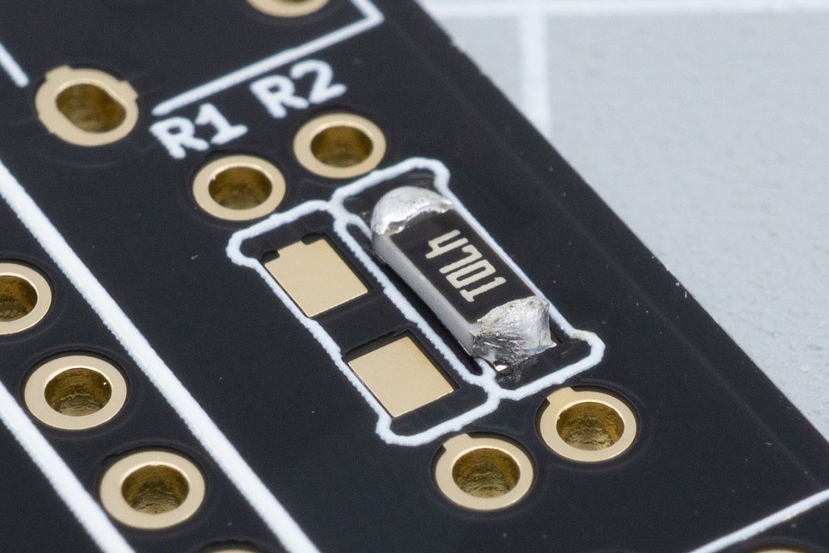
The first resistor fully soldered, with both joints looking good.
Repeat this process for the other resistor.
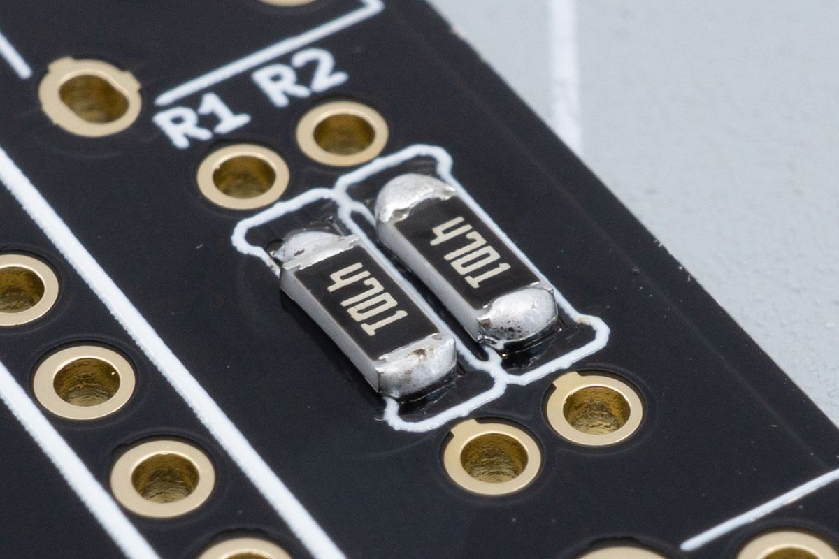
Both SMD resistors soldered.
RGB underglow
Light shining down on your desk from the bottom of your keyboard. Learn how to solder RGB underglow LEDs.
Switch sockets
Switch sockets allow for replacing your switches in the future without having to desolder. Here's how you install them.

