Batteries
You should perform this step if you are building a wireless keyboard. If not, you can go to the next step using the button below.
Don't be afraid of the length of this page. We added extra pictures and different configurations to make sure you install the battery correctly because of the warnings above.
If you’re socketing your controller, it's possible to install the controller first, remove it from its sockets, install the battery and insert the controller into its sockets again. To ensure there is enough space for the battery before soldering the socket pins, we do recommend following the steps below first.
Unfortunately, due to strict restrictions on shipping batteries internationally, splitkb.com currently does not sell batteries. You will have to acquire batteries somewhere else. We can recommend the following stores, or their resellers:
Some batteries you can purchase from these sources will have a matching JST-PH plug on the end of their cable. You can insert these batteries directly into our boards, after double-checking the polarity.
You should follow these steps:
- If you've installed a JST jack to your keyboard, and your battery came with a JST-PH plug, you can follow Installing a battery using a JST plug.
- If you've installed a JST jack to your keyboard, but your battery did not come with a JST-PH plug, or if your battery did come with a plug but it's oriented incorrectly for the jack, you can follow Adding a JST plug to your battery.
- If you couldn't install a JST jack to your keyboard, follow Soldering a battery directly to the board.
If you're unsure about what to do, read all the steps below so you have an idea of what the process entails. You'll probably see which steps match your situation then.
Installing a battery using a JST plug
Before installing the battery completely, double check the polarity. The black cable should go to the minus (-) and the red cable should go the plus (+).
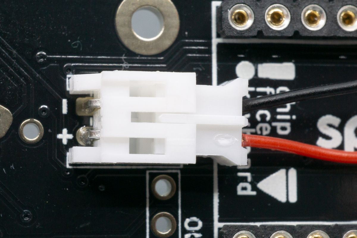
Plugging in the battery using its JST plug. Line up the red cable with the + side. It's not yet fully plugged in here.
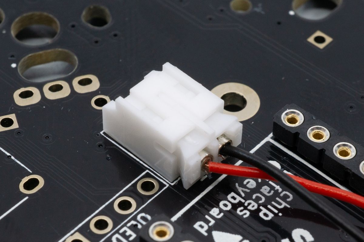
The battery, now fully plugged in.
Small batteries, such as those with a capacity of 80mAh or 110mAh, can usually be placed between the PCB and the controller. Route the cabling, place the battery between the headers, and finally install your wireless microcontroller in the next step.
You want to avoid creases or hard bends in the cables. Bending or folding the cable can cause the cable to break internally, which will cause your battery to not work as intended.
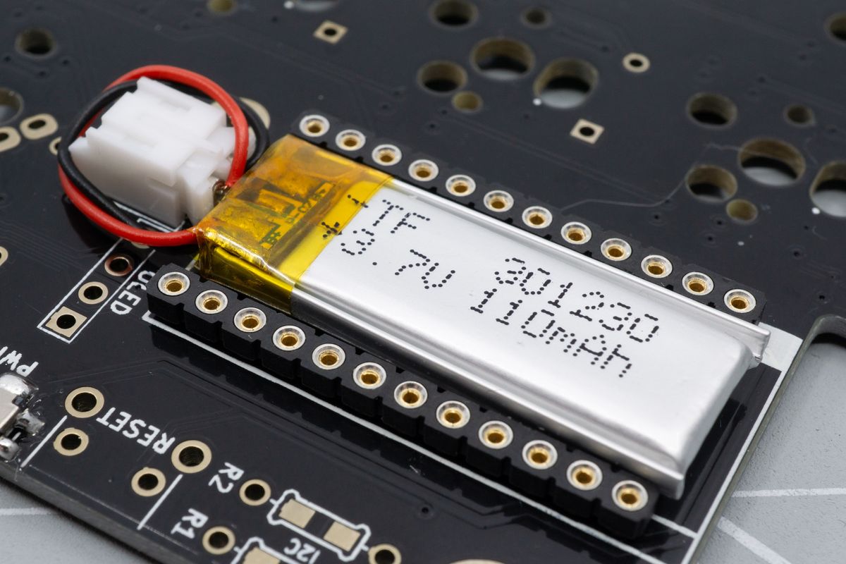
The battery can be placed between the controller sockets or headers.
Next up, perform a dry fit of your controller on top of its sockets or header. You can follow the steps for installing the sockets, just don't do any soldering yet. You'll be able to gauge the required height for your battery.
Once the battery and the sockets and any pins or headers are fitted, you can then remove the battery and solder your controller to its pins or headers if you're using sockets. The battery now fits underneath, and you can reinsert your controller.
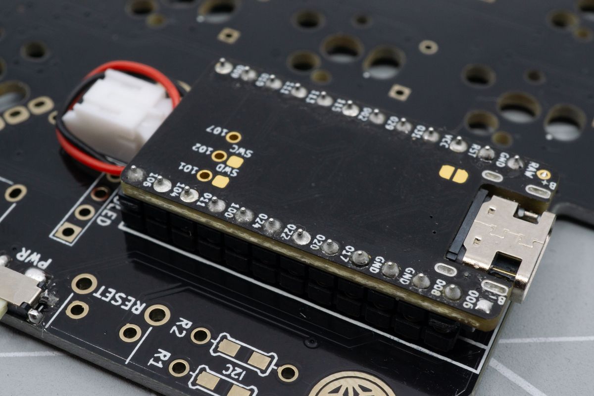
The controller pressed on top of the battery.
Congratulations! You can now continue with the next step: Rotary Encoders.
Unplugging a battery
If for whatever reason you need to remove the battery, it is always recommended to not pull on the wires directly. The plug can be quite small to remove with your fingers. We recommend using tweezers instead.
If your battery is installed between the PCB and the socketed microcontroller, you should try and remove the microcontroller from its sockets first.
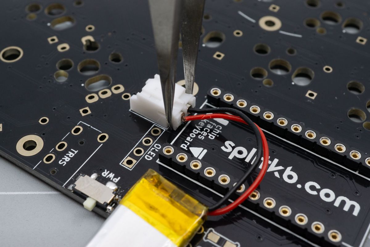
Unplugging the JST connector is easier using tweezers or pliers.
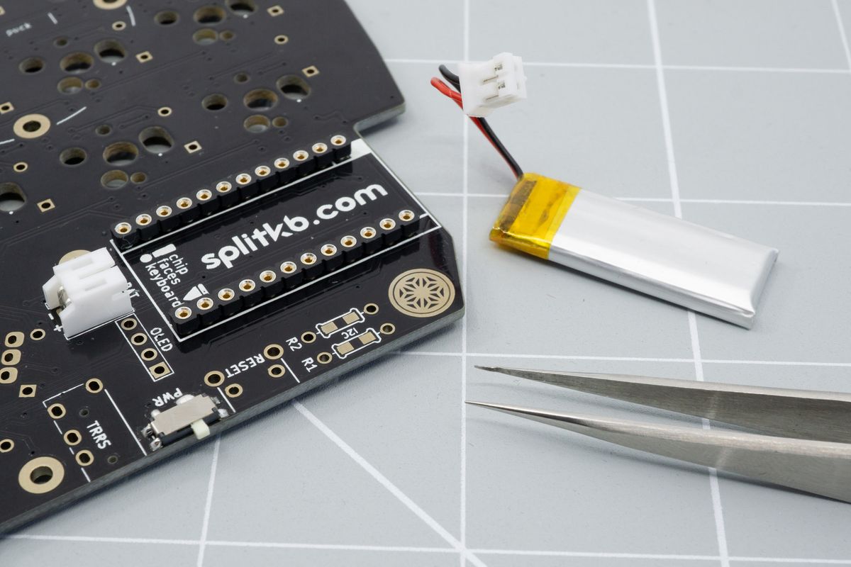
Once unplugged, you can reuse the battery for a future project or dispose of it at an appropriate facility.
Soldering a battery directly to the board
When soldering your battery directly to the board it is important to always make sure that the red and black wire never touch each other. This is can happen quicker when soldering directly to the board instead of the other methods.
You will need the battery and your PCB. Make sure to tape the red wire if it's not already before starting as this will limit the chances of creating a short. Our boards have the pads quite close together, even for the boards where a JST jack doesn't fit, so make extra sure that you don't make any shorts.
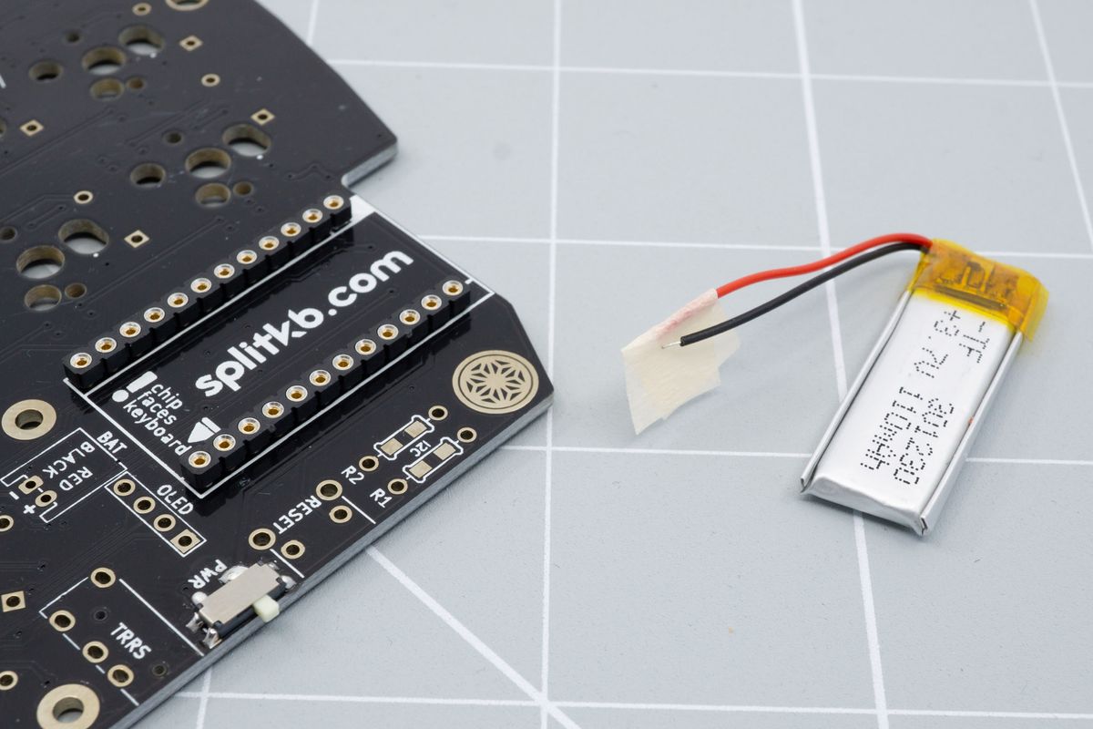
Any tape can be used to isolate one of the battery's wires.
You can strip a larger length of the black wire to be able to insert it more easily in the the board.
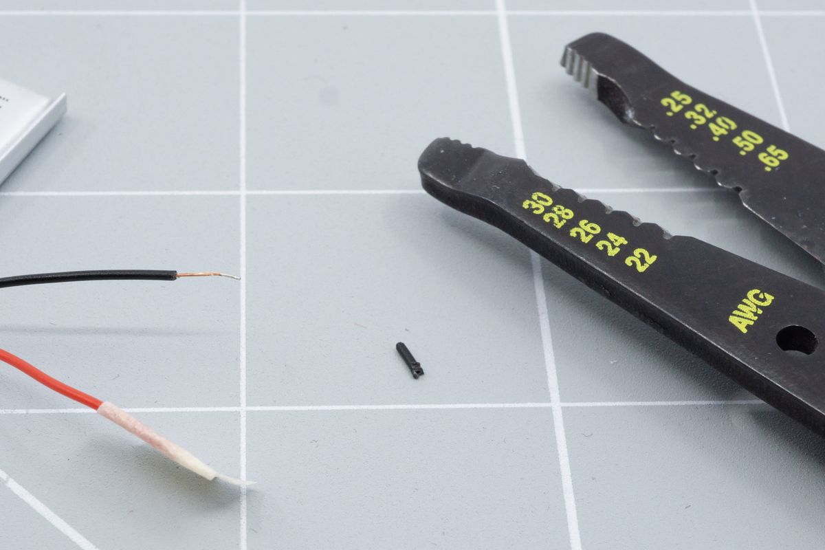
The black wire after stripping it, exposing a few extra millimeters of copper.
Insert the black cable into the board in the minus hole, this should also say "black" on most boards. You can fold the wire on the back side so it stays in place.
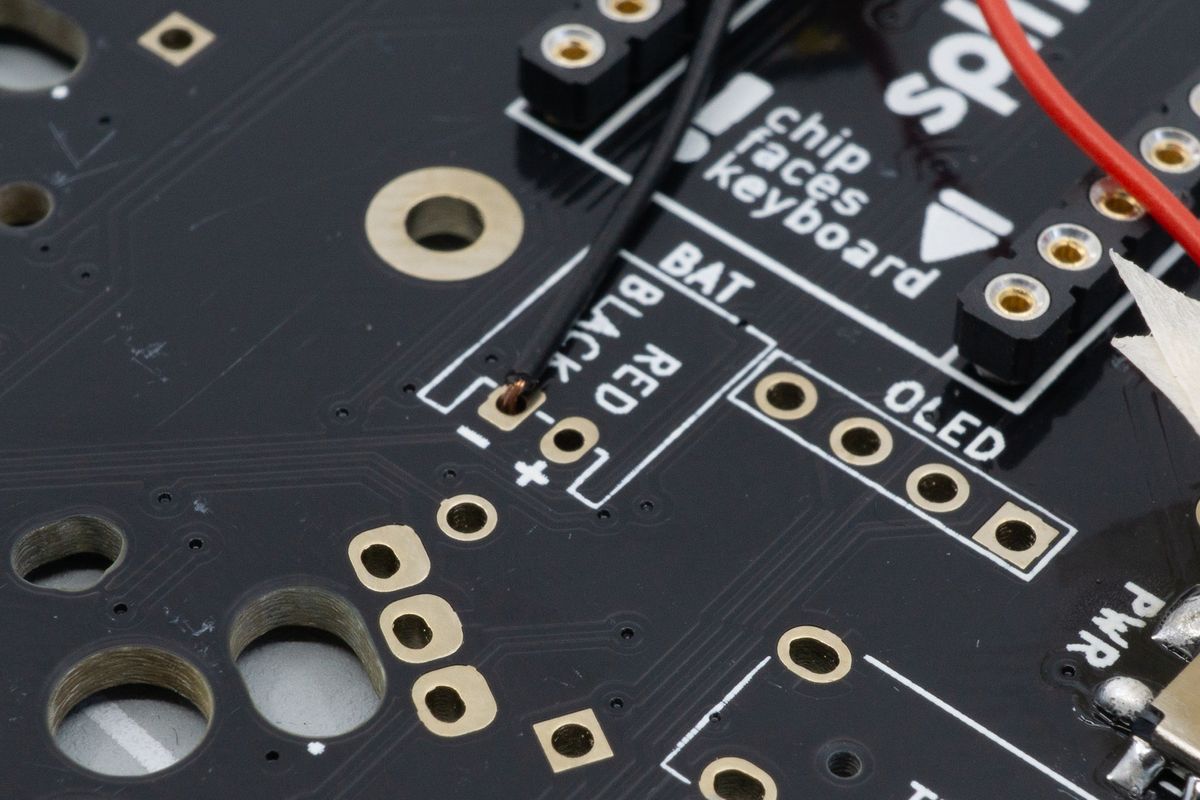
The wire is inserted from the top side of the board. If you're placing your battery differently than we recommend, it's fine to insert it from the back side too, as long black connects to - and red connects to +.
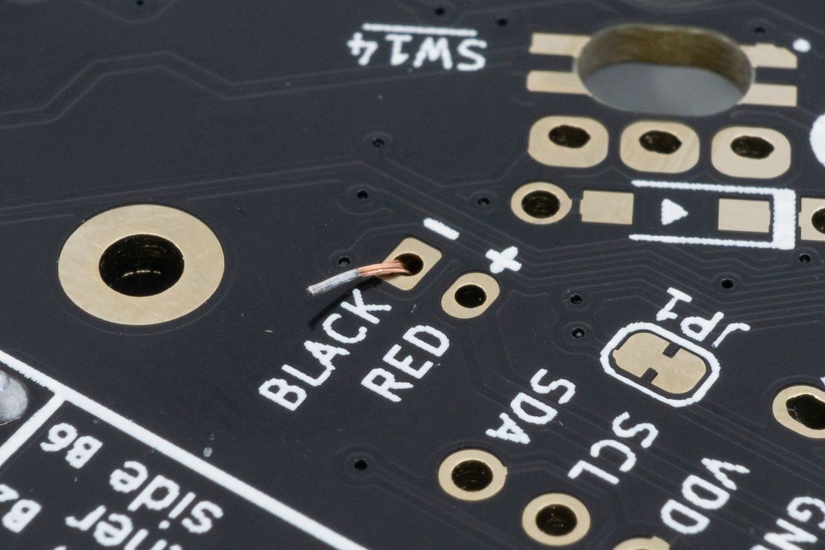
The wire can be folded for it to stay in place easier while you work.
Solder both the front and back. Try to not heat the wire for too long. That may damage the battery and also melt part of the wire insulation. If you happen to melt some of the insulation, consider applying a little bit of electrical tape around the wire to restore the insulation.
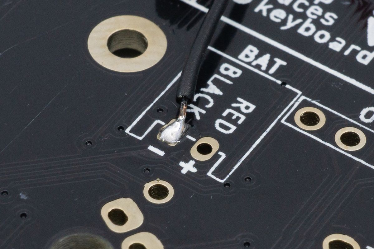
The wire soldered from the top side.
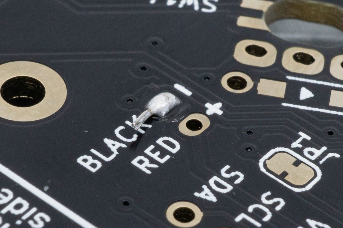
The wire soldered from the back side, as well.
Cut off any extra parts sticking out with flush cutters. After that also strip the red wire and carefully insert it into the PCB as well. Again, you do not want want to make contact between the two wires.
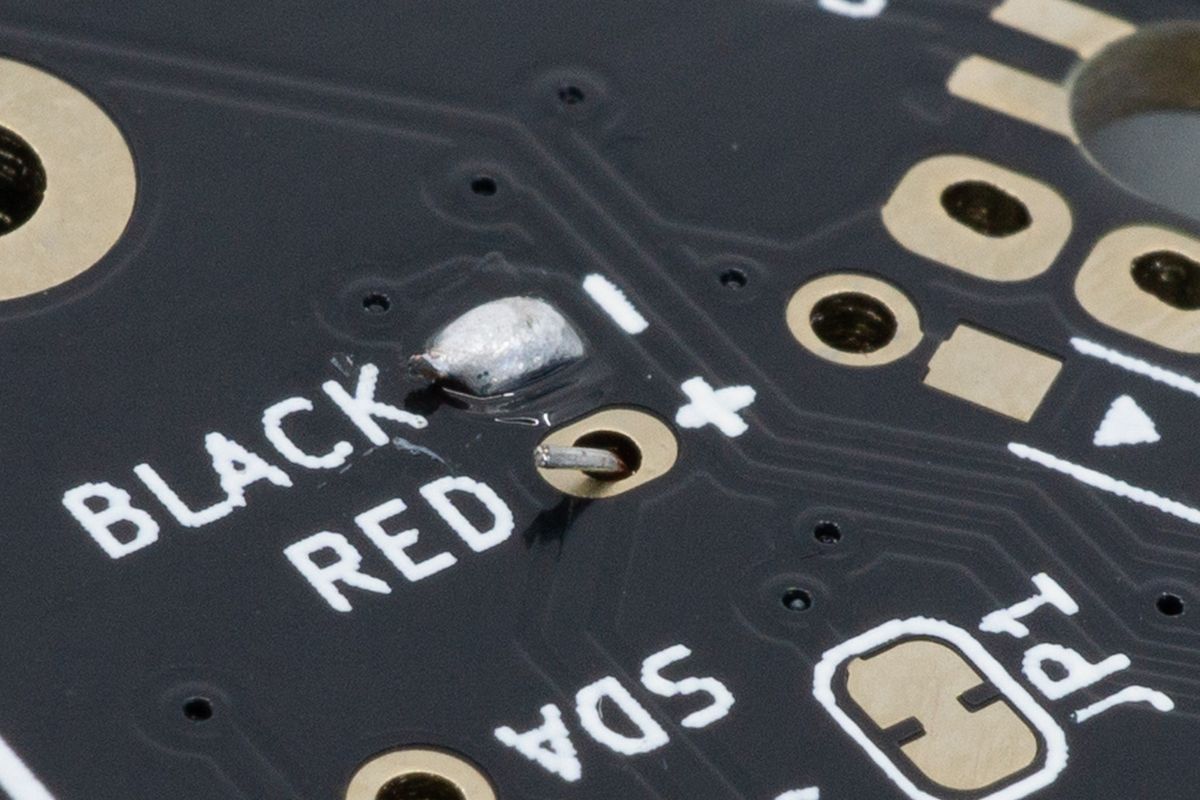
DSC02097.jpg.
Solder both the front and the back again. The finished product should look similar to this.
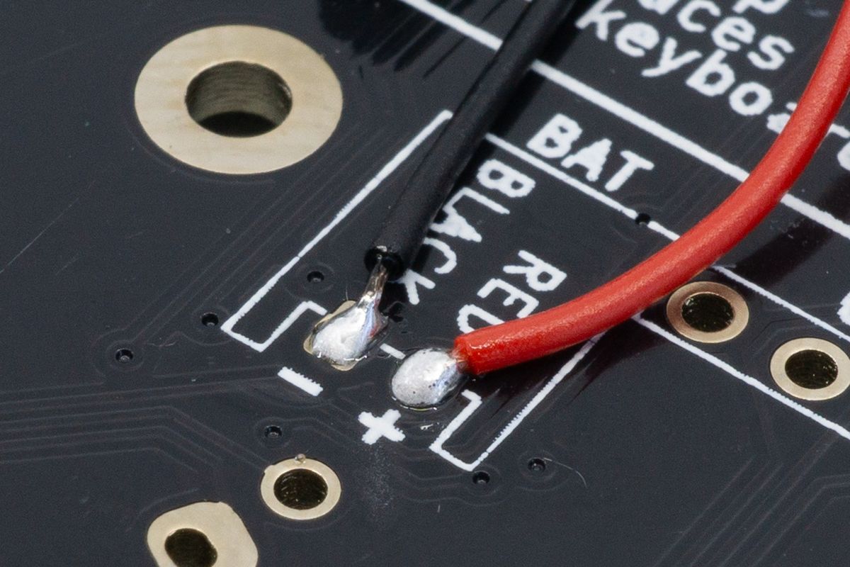
Both wires soldered from the top.
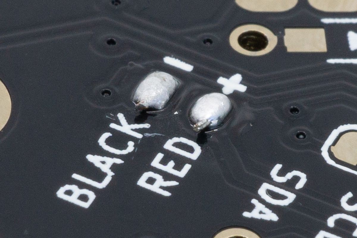
Both wires soldered from the back.
To minimize the chances of creating a short when continuing building the keyboard and even for day to day use, it is recommended to use some electrical tape to cover up the exposed pads. This way a loose wire or something similar can't create a short when it comes in contact with your PCB.
Alternatively, you can also use a dab of hot glue.
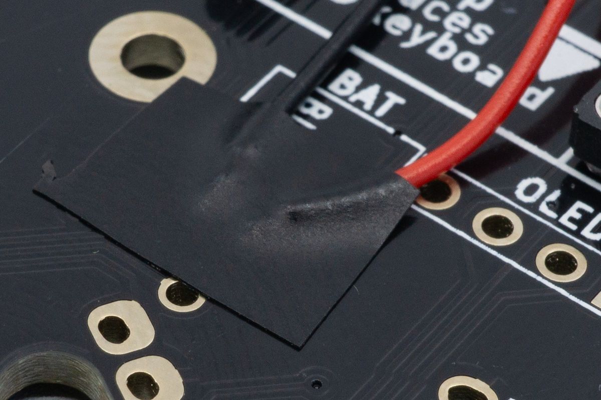
Electrical isolation tape stuck on the front side. You can also use Kapton tape, and scotch tape may work in a pinch.
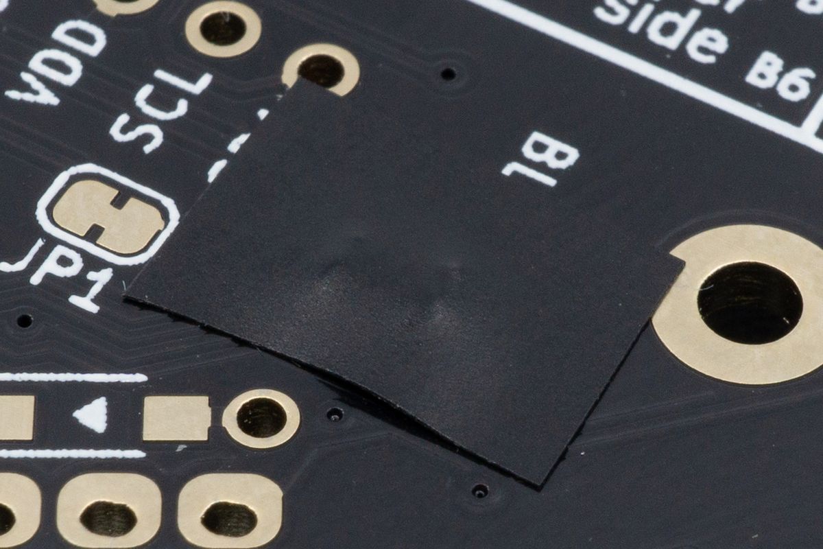
Electrical isolation tape stuck on the back side.
When using a small enough battery, you can place it between the headers and the wireless microcontroller as shown below. Make sure the route the wires neatly to avoid creases in the cable.
You want to avoid creases or hard bends in the cables. Bending or folding the cable can cause the cable to break internally, which will cause your battery to not work as intended.
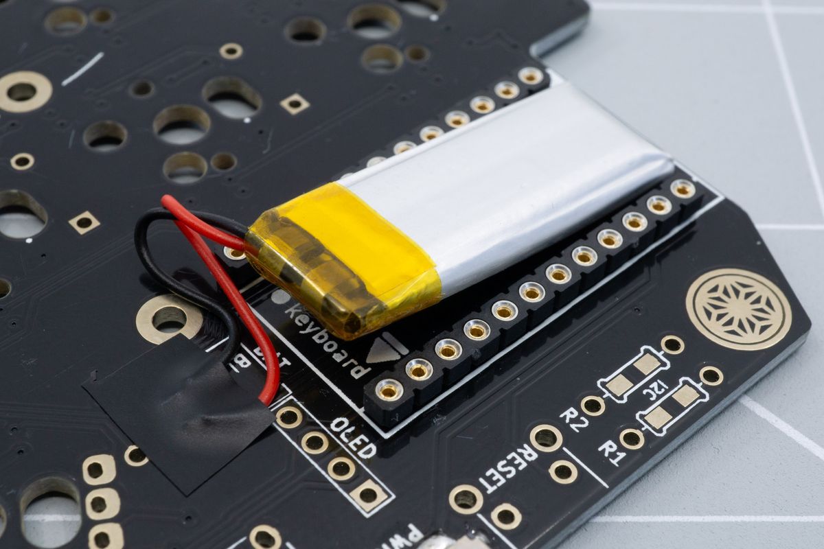
Placing the battery between the controller sockets.
Finally, you can solder your microcontrollers by going back to the previous step.
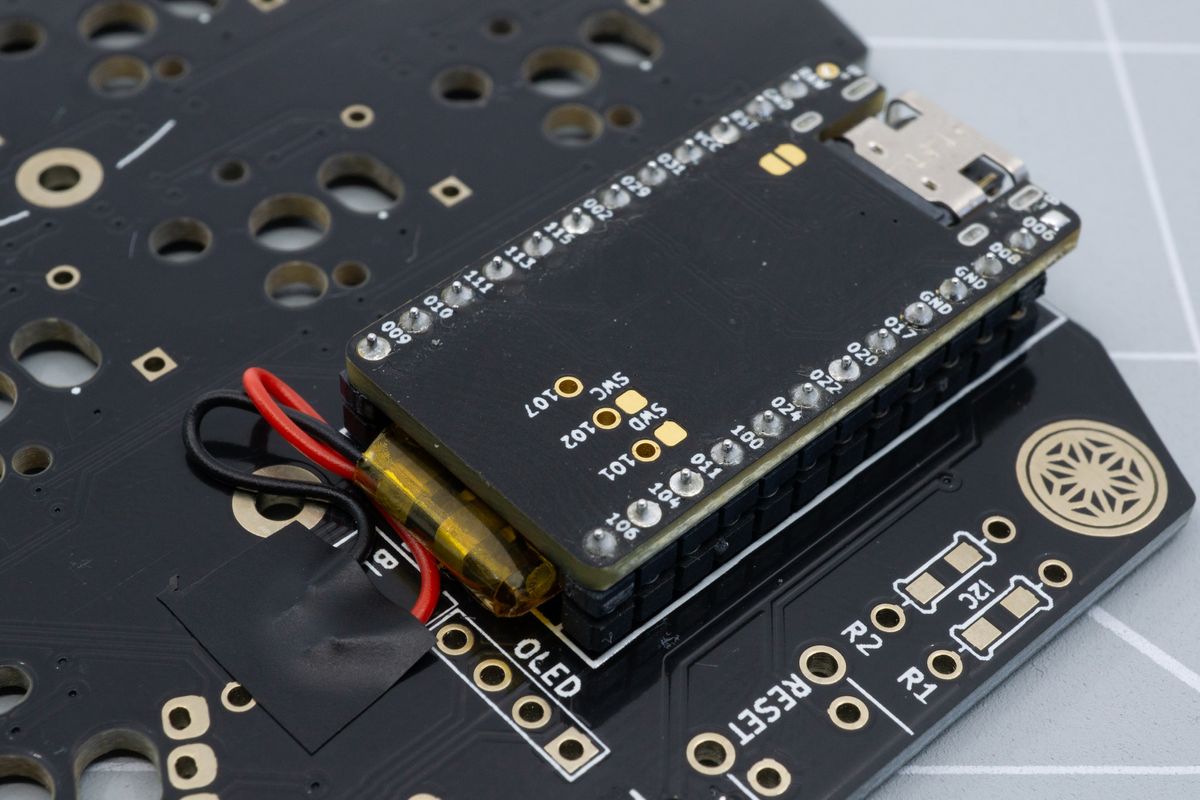
An installed microcontroller sitting on top of the battery.
Congratulations! You can now continue with the next step: Rotary Encoders.
Adding a JST plug to your battery
You will of course need the battery, a JST-PH body and two connectors. The body and connector will be purchasable from the splitkb.com website soon. The battery here has already stripped cables and a piece of tape on the positive (red) cable. Keep this piece of tape on there or add some tape yourself if it’s not on there by default. Also strip the black cable if it’s not stripped by default.
You can use a specialised JST crimping tool. This makes the job very easy, but the tool can be quite expensive. Alternatively, you can also use small pliers. How to use either of these tools is explained below.
First, let's ready the cables for the connector. These steps apply to both tools.
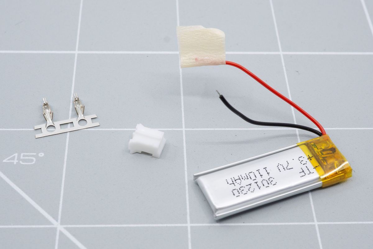
The necessary parts, from left to right: the connectors, the JST-PH body and the battery you're going to add the plug to.
Remove the connectors from the strip by bending it forward and backwards until it breaks off.
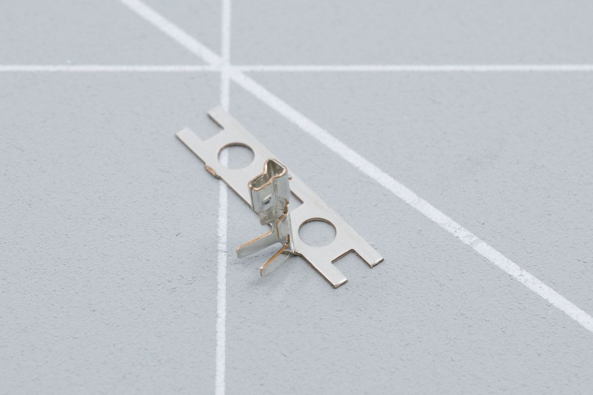
If using just your fingers is awkward, you can also use pliers to hold the metal strip while you move the connector back and forth.
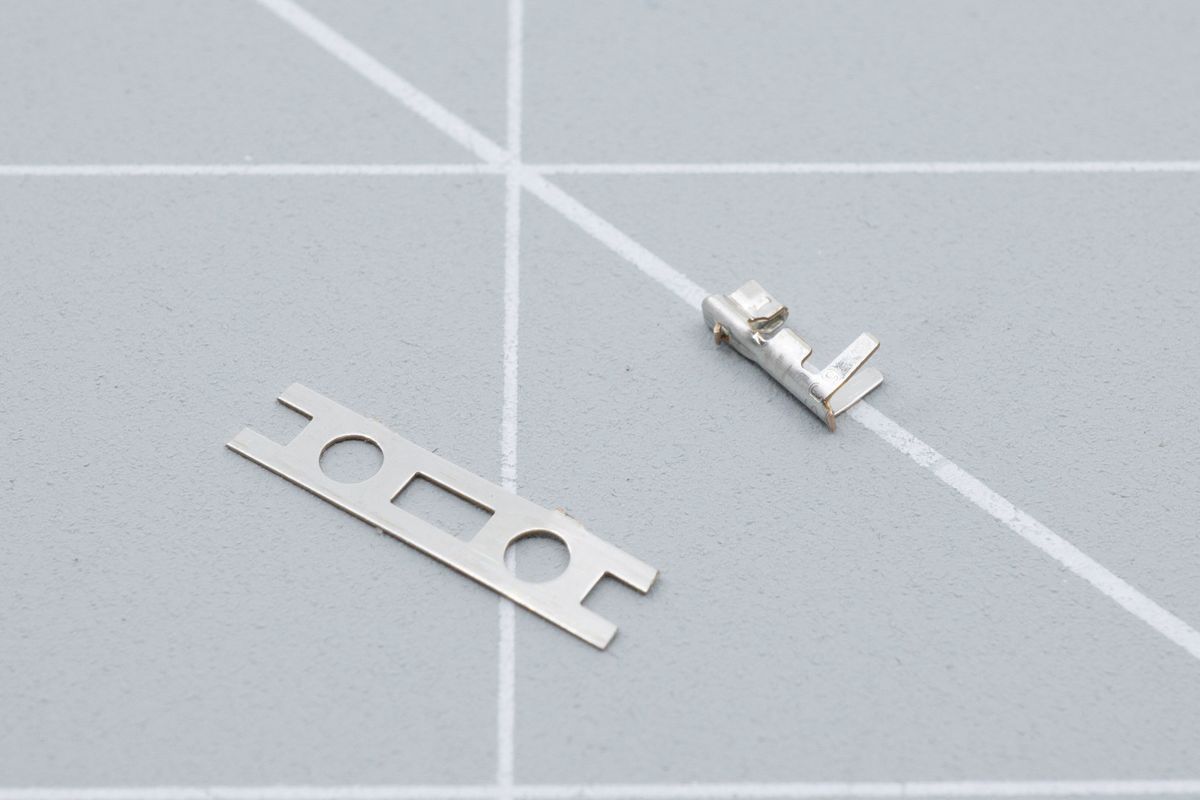
The connector will snap clean off the strip.
Using an appropriate JST crimping tool
Insert the connector in to the JST crimping tool, use the 1.3mm wide slot. Make sure it’s all the way in by pushing the longer legs against the tool. Don’t squeeze the crimper too hard yet!
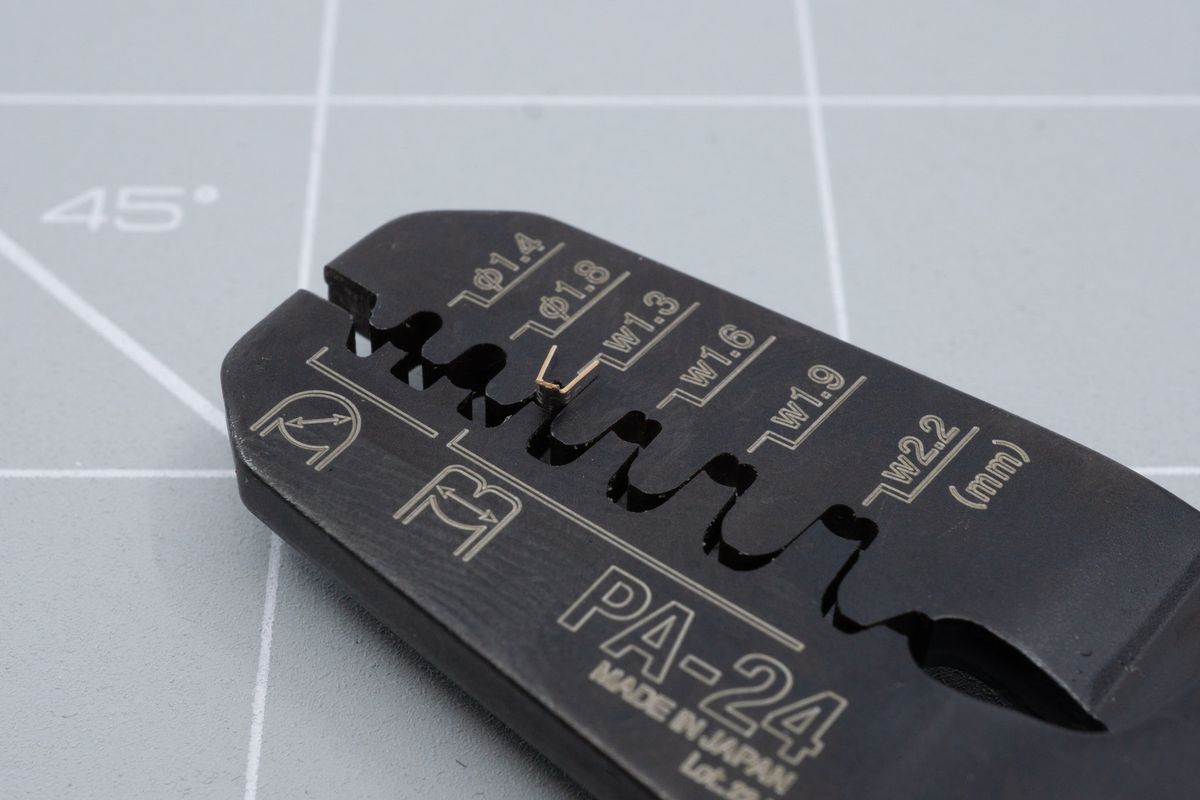
A crimping tool makes the job easy.
Insert the cable into the connector. Make sure you don’t push in the cable too far. The exposed metal should be parallel with the crimping tool. When it’s in position, squeeze the crimping tool hard.
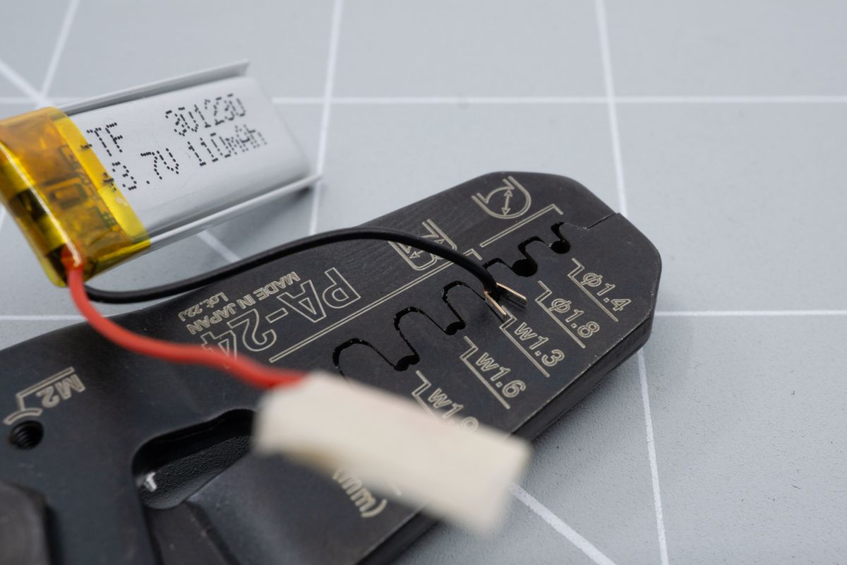
Crimping the first part of the connector.
It should look similar to this.
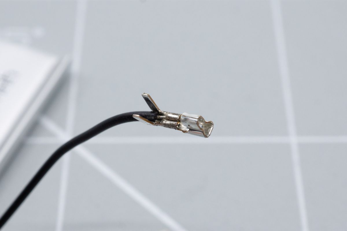
The first part of the connector makes the electrical connection between the cable and the connector.
Now stick the longer leg part in to the 1.6mm crimping spot and squeeze it tight as well. You should end up with something looking like this.
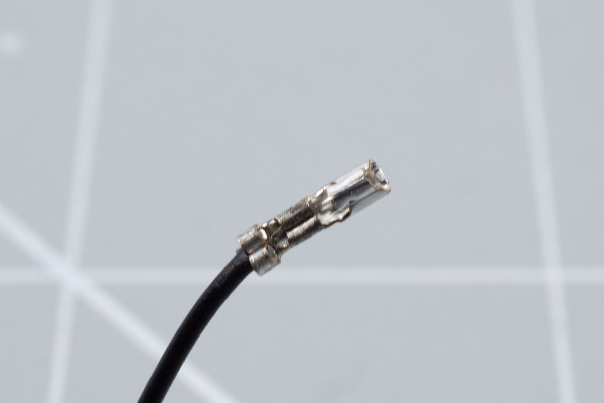
The second part clamps down the cable housing, to alleviate stress from the electrical connection.
Using a JST jack with pliers
Using pliers is quite a bit trickier. You should hold the connector in the pliers like the picture below so when you when you place the cable in the connector you can squeeze it. Don’t squeeze too tight yet. We just want to hold it like this to be able to bend the metal parts over the cable.
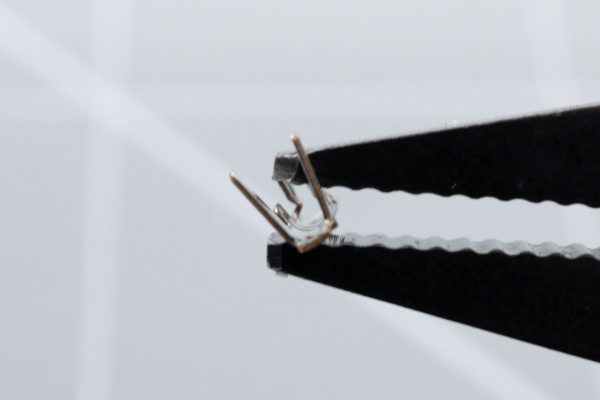
Clamp the connector, one leg at a time.
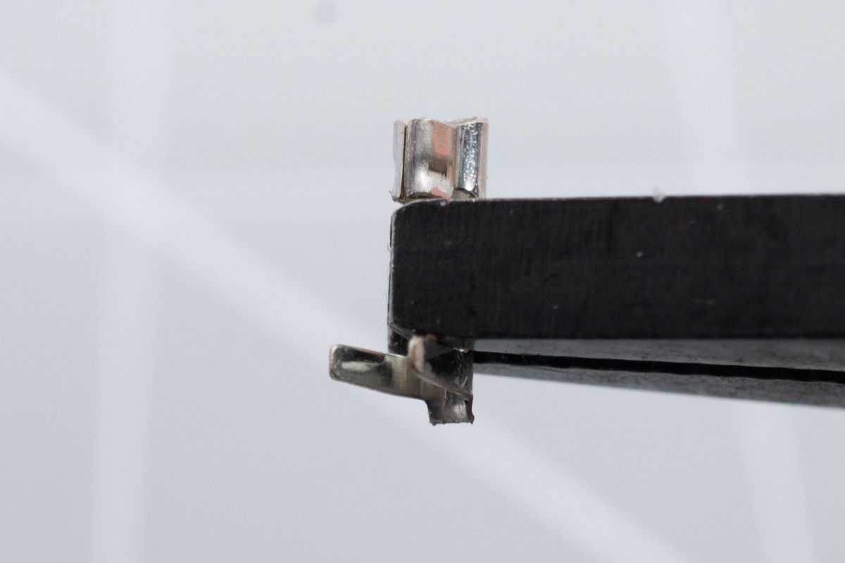
Viewed from another angle. Don't squeeze it just yet.
Insert the cable and bend over the legs over the cable. This can be quite tricky. The red positive cable is pictured here but always start with the black wire!
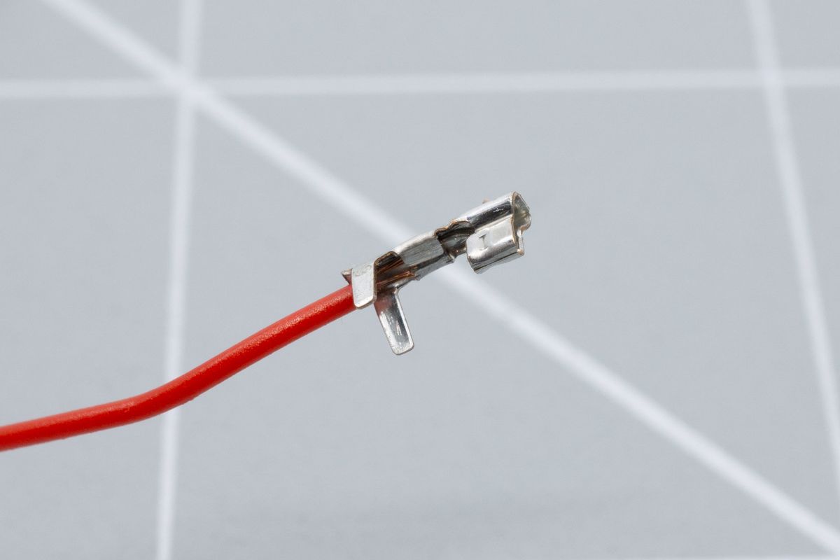
The cable, clamped in place by the first set of connector legs.
When the cable doesn't pull out anymore, you can also bend over the longer legs.
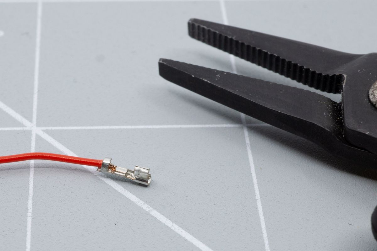
The first leg bent of the second set of legs on the connector, which relieves force from the electrical connection.
Of course, finish by clamping the last leg, too.
Inserting the connectors into the JST plug
Before inserting the JST connector into its body, double check to make sure you put the correct polarity in the correct spot. The easiest way to do this, is to look for the little plus and minus sign on the PCB.
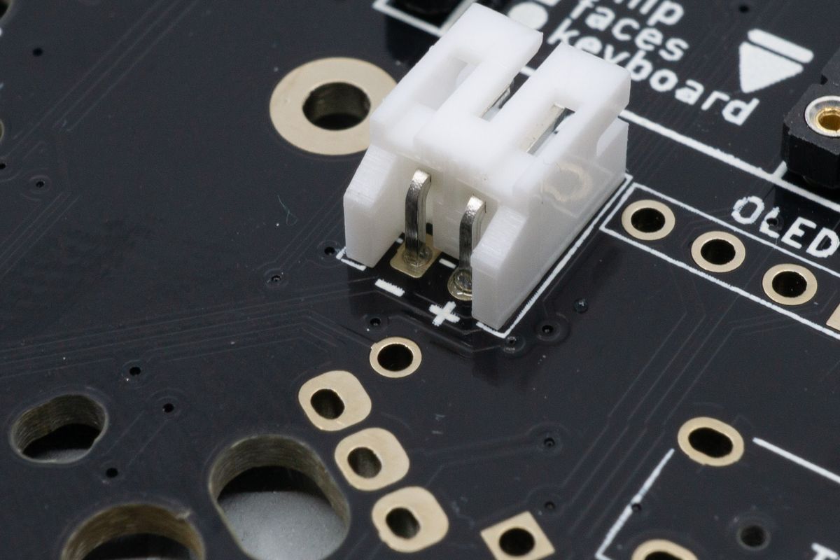
The minus and plus icons show which side should take ground (black, minus) and the voltage supply (red, plus).
The black cable should be put in to the left side when looking from the front, with the tab part sticking up.
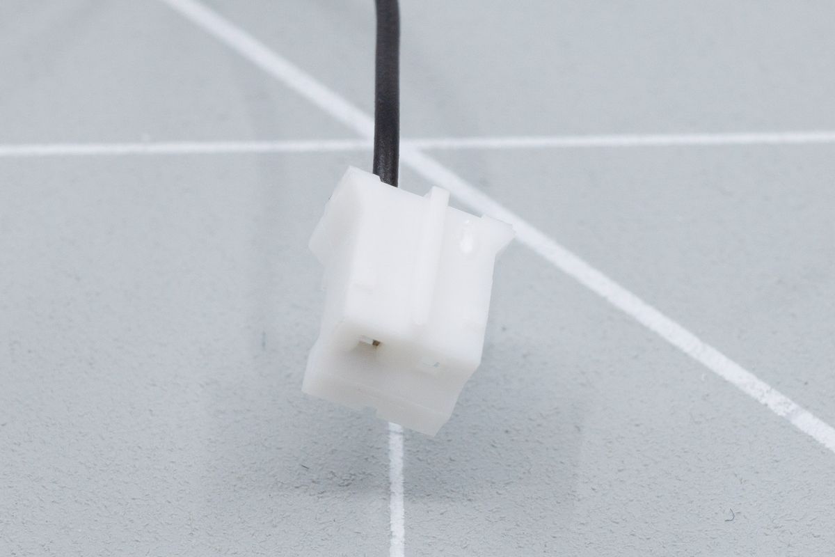
The plug housing shows a fin facing upward, which slides into a similarly shaped slot on the connector.
When inserting, make sure the connector is in the correct orientation compared to the plug. Look at the image and compare with your own work.
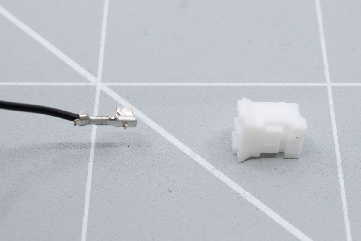
Readying the cable for insertion into the plug.
Make sure to push the connector al the way in to the JST plug. You may or may not hear a little clicking noise. You can confirm it’s all the way in when the metal lip is above the little plastic wedge.
If you used pliers, it might not fit directly and you may need to squeeze the sides of the connector and try again.
After inserting the black wire, do the same steps for the red wire.
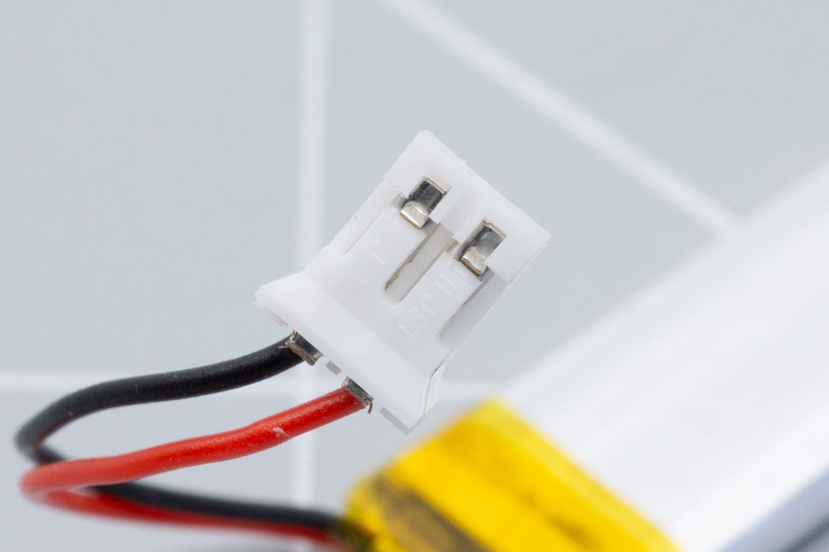
Both wires inserted into the JST plug. A little metal tab keeps the cables in place.
Congratulations! You added a JST plug to your battery. You can now go back to the top of the page and follow the steps of installing the battery.
Microcontrollers
The brains of your keyboard.
Rotary encoders
Rotary encoders allow for both rotation as well as push actions.

