Reset buttons
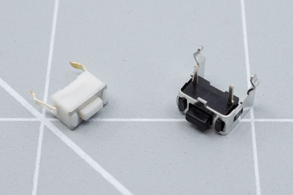
Two tactile buttons. On the left is the straight button, on the right is the angled button..
Your kit will include a set of reset buttons. Most kits will use angled reset buttons, but some will use a straight one.
Angled button
If your kit uses straight reset buttons, please skip to the straight button section on this page.
Angled reset buttons are located on the edge of the board, near the microcontroller. You can recognise the footprint by its "RESET" text and the four holes.
You'll always install the reset button on the top side of the keyboard.
If you can't find the footprint, your board may be using straight reset buttons, which are covered in the next section.
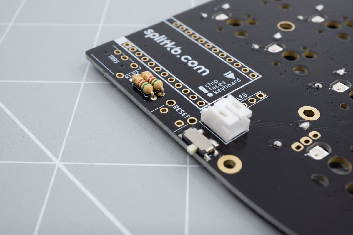
The footprint for the angled reset button, with its RESET text and four holes.
Insert the button into the top side of the PCB. It can take a little wiggling or force to push the switch in.
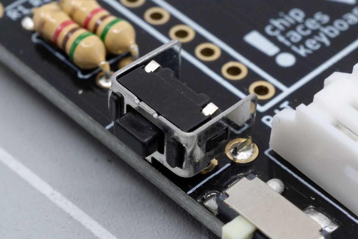
The angled reset button inserted into its footprint.
Due to the shape of the legs it will remain in place when you flip the PCB over to solder it.
Solder all legs of the reset button, and repeat for the other half of your keyboard.
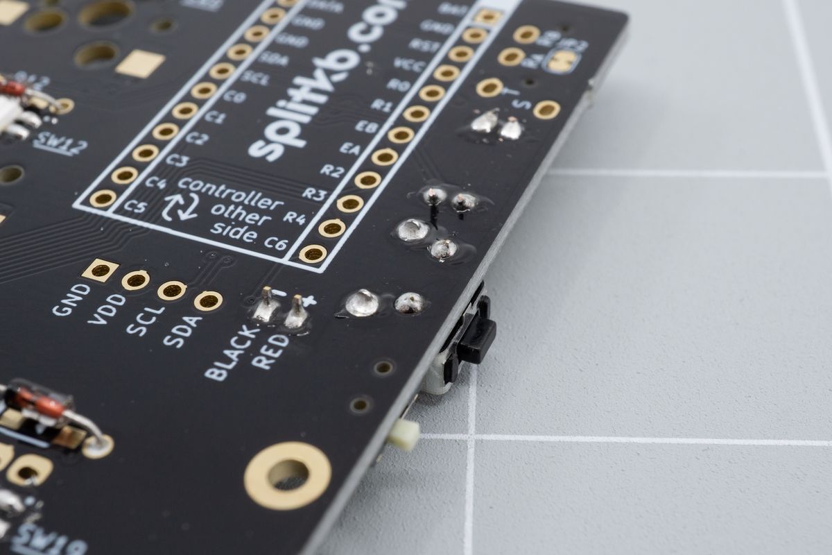
The angled reset button, soldered, looking from the bottom side of the PCB.
There's no need to cut any leads off, as there's no excess length remaining.
Straight button
If you just installed the angled reset buttons, please continue to the next page.
Straight reset buttons are located away from the edge of the board, but still near the microcontroller. You can recognise the footprint by its "RESET" text, two holes and a rectangular outline.
You'll always install the reset button on the top side of the keyboard.
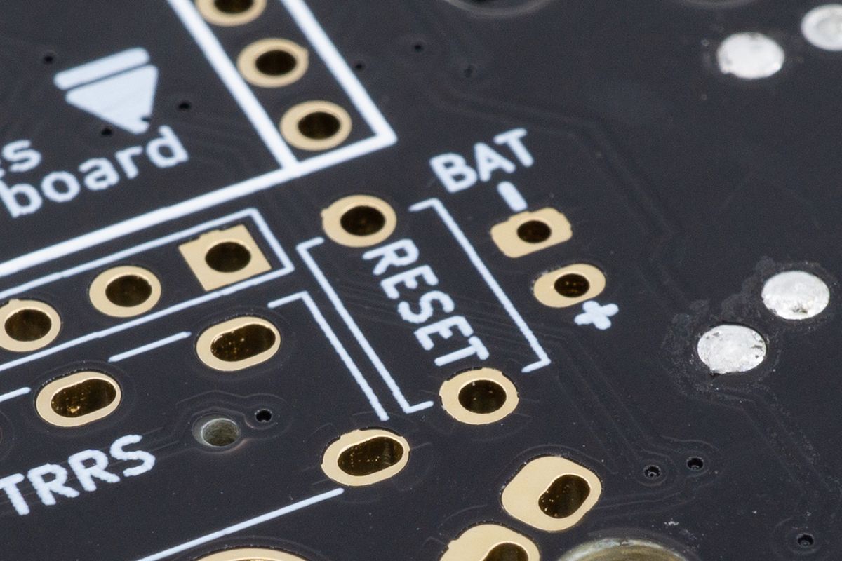
The footprint for the straight reset button, with its RESET text, two holes and rectangular outline.
Insert the button into the top side of the PCB. It can take a little wiggling or force to push the switch in.
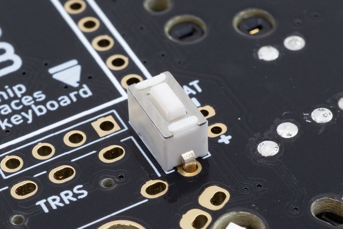
The straight reset button inserted into its footprint.
Due to the shape of the legs it will remain in place when you flip the PCB over to solder it.
Solder both legs of the reset button, and repeat for the other half of your keyboard.
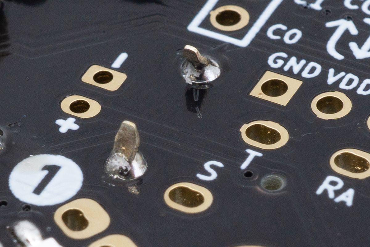
The straight reset button, soldered, looking from the bottom side of the PCB.
There's no need to cut any leads off, as there's not much excess length remaining.
JST jacks
The JST jack allows you to connect and disconnect your wireless keyboard's battery without soldering.
TRRS jacks
TRRS jacks allow you to connect the halves of a split keyboard together with a TRS or TRRS cable.

