OLED sockets
You should perform this step if you opted to use 4-pin sockets for the OLED displays. If not, you can go to the next step using the button below.
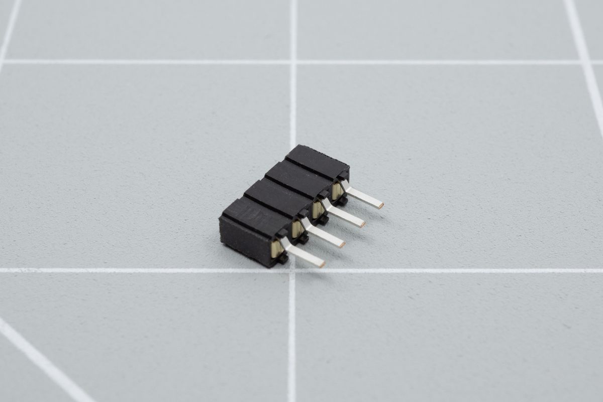
The bottom side of a 4-pin socket.
Insert the socket from the top of the PCB. You can use a piece of electrical or scotch tape to hold it in place.
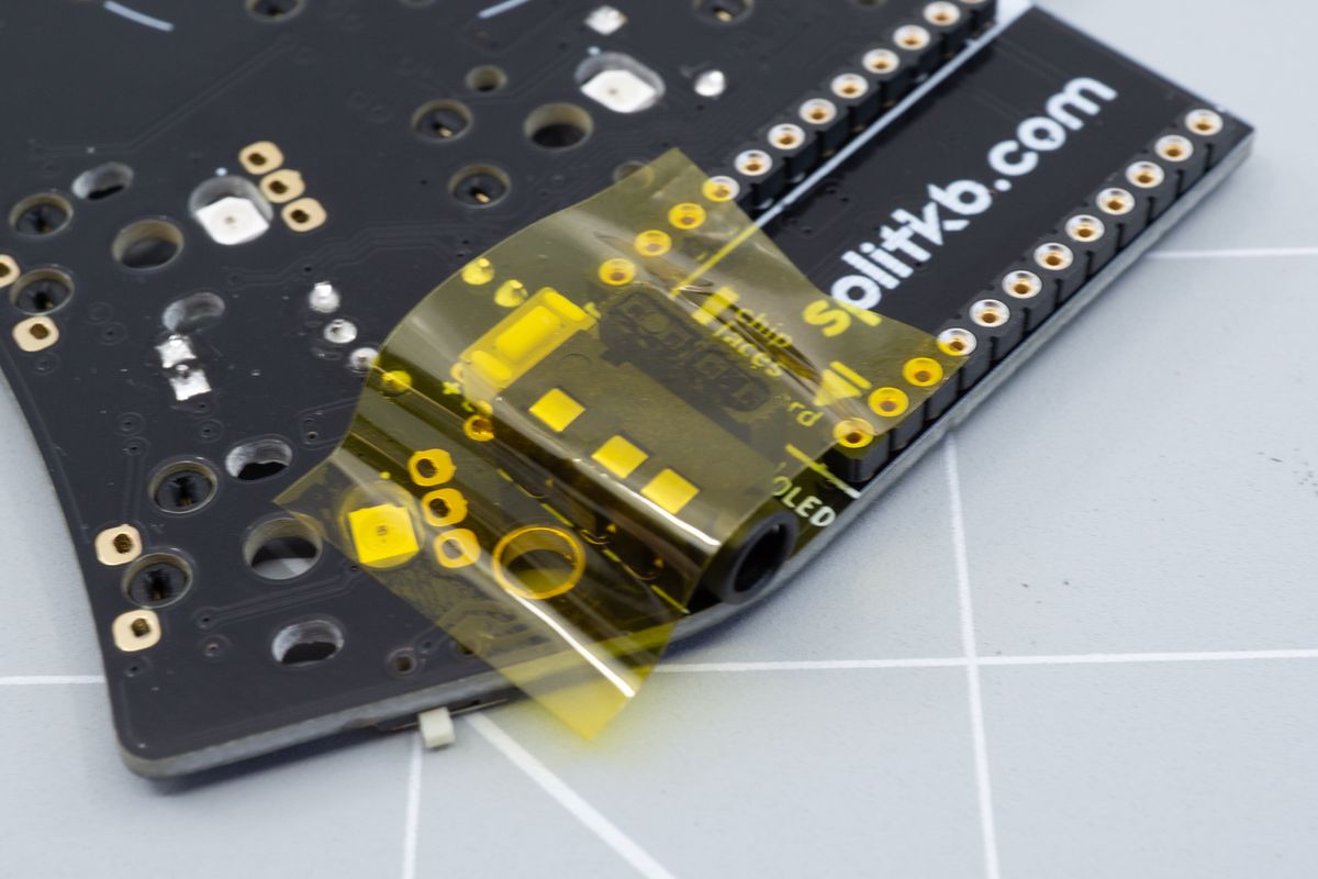
Some tape holds the 4-pin socket in place. As the socket sits lower than the TRRS jack, it's best to use tape so it won't drop out once you flip the PCB over to solder it.
Flip the PCB and solder one single pin of the socket.
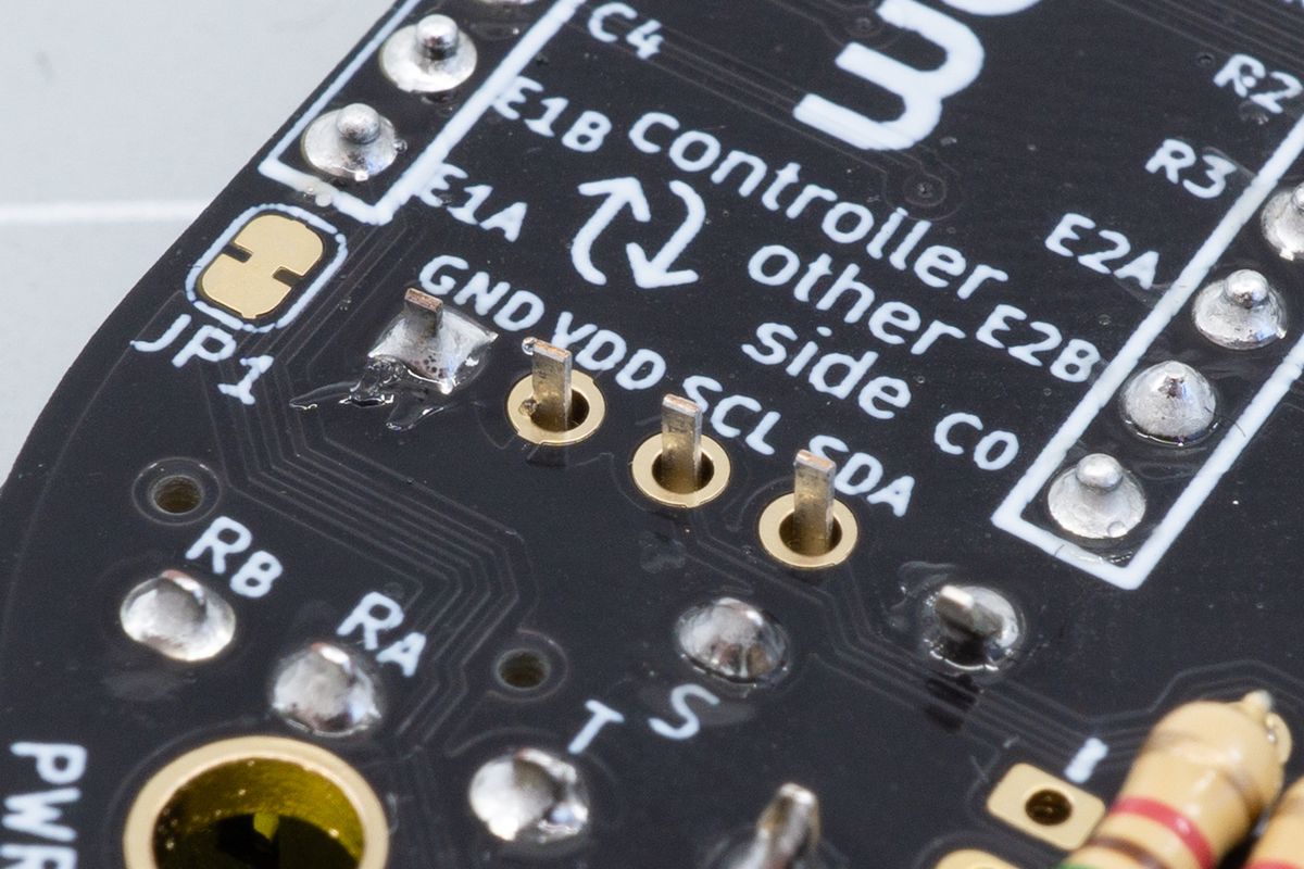
The first pin of the socket soldered. The order doesn't matter much, as long as you only solder one pin to start with.
Then, flip the board around again and check whether the socket is aligned straight. If it’s not, heat up the solder joint and move the socket around until you’re happy with how it looks.
Lastly, solder the remaining three pins.
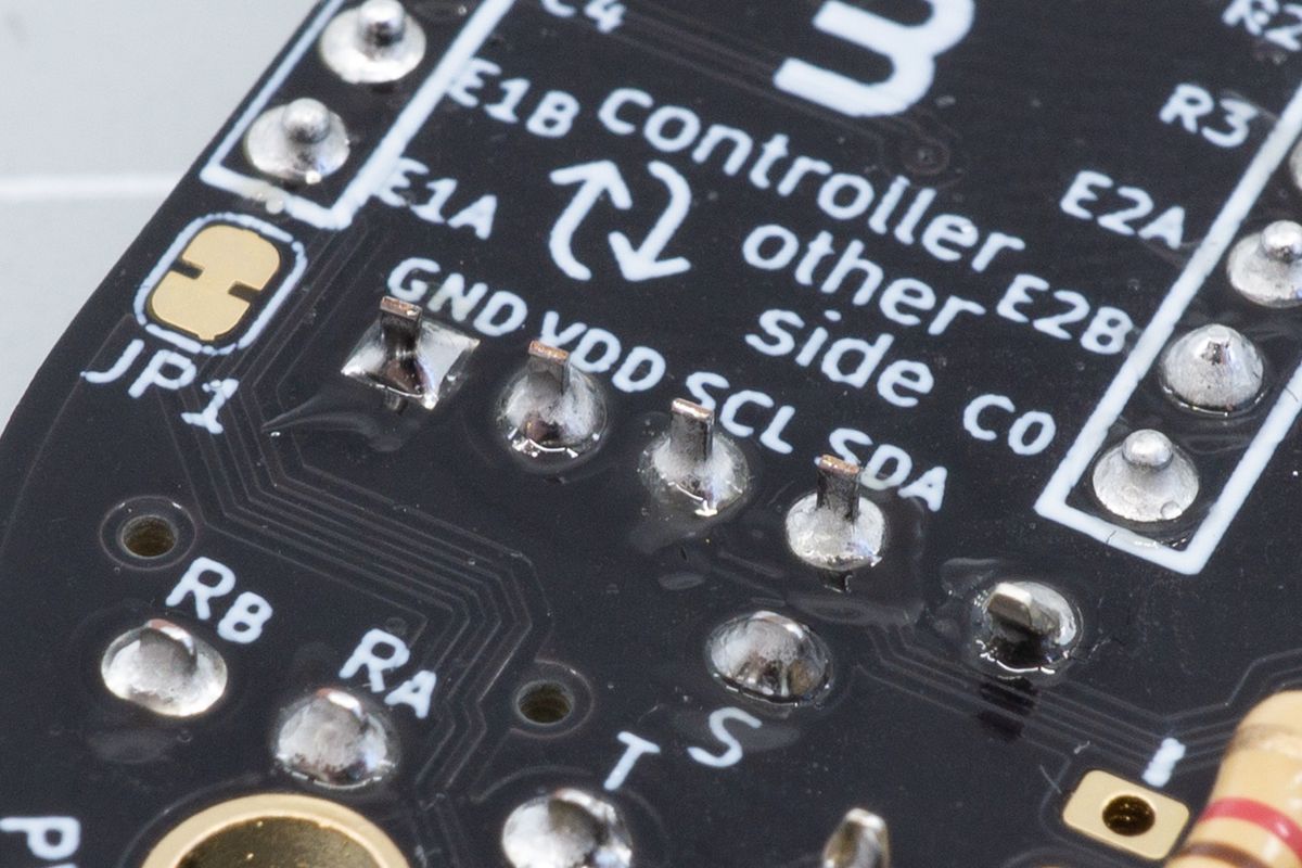
The soldered socket, looking at the bottom side of the PCB.
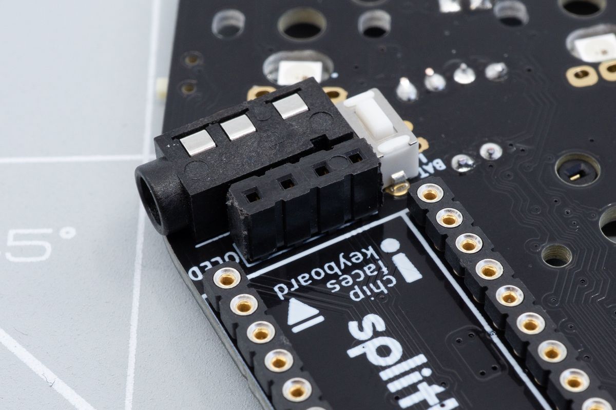
The soldered socket, looking at the top side of the PCB. Notice how it sits straight, and flush with the PCB.
TRRS jacks
TRRS jacks allow you to connect the halves of a split keyboard together with a TRS or TRRS cable.
Microcontrollers
The brains of your keyboard.

