Diodes
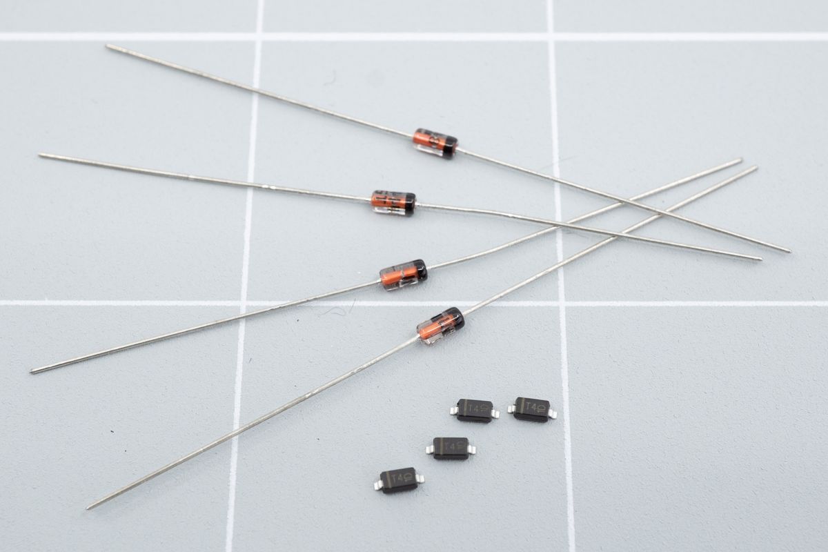
A few through-hole and SMD diodes.
We start the build with the diodes. They are little components which only allow electricity to flow in one way, and they are required for the keyboard to properly tell key presses apart. Your kit will come with either through-hole or SMD diodes.
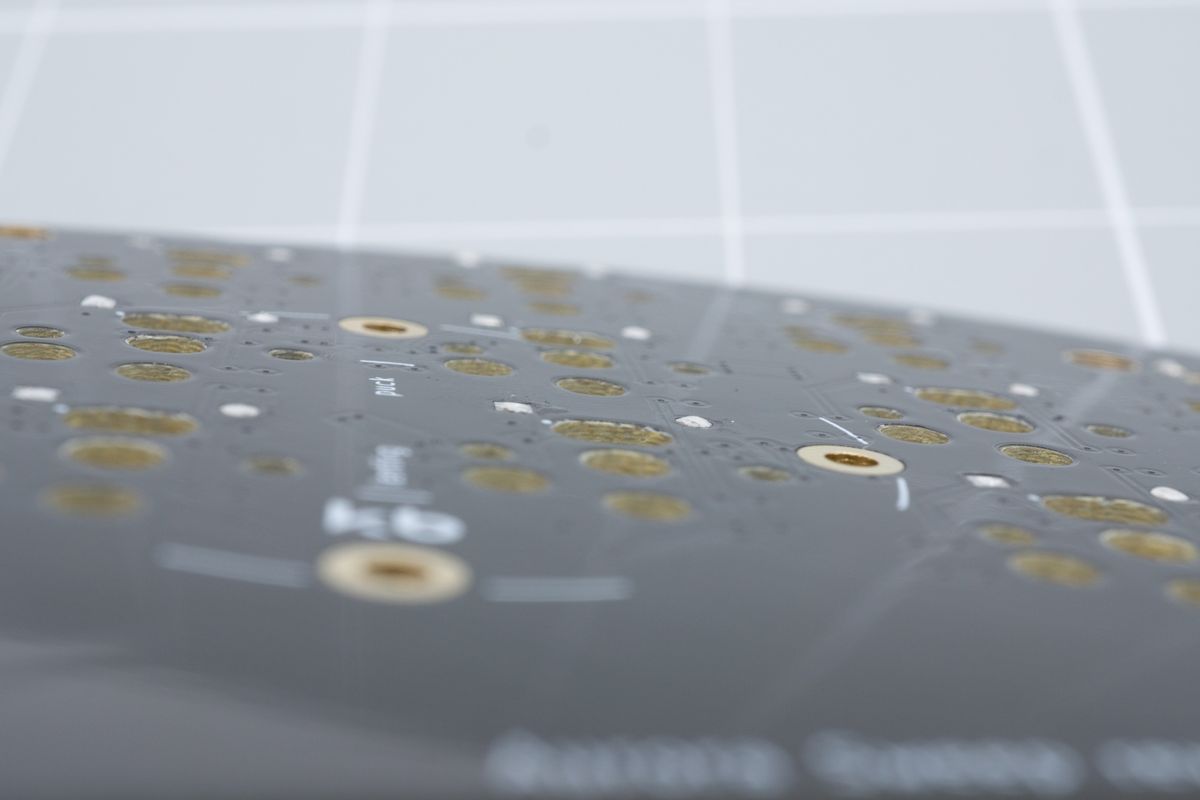
Flushly cut through-hole diodes.
Through-hole diodes
If you’re using SMD diodes, please skip to the SMD diodes section on this page.
The diodes positions are usually all placed next to switches, all oriented the same way where possible. They’ll be marked with a D followed by a number, like D14.
Start by familiarizing yourself with their orientation. On through-hole diodes, there’ll be a black line which will need to match up with the square hole and the thick white line on the PCB.
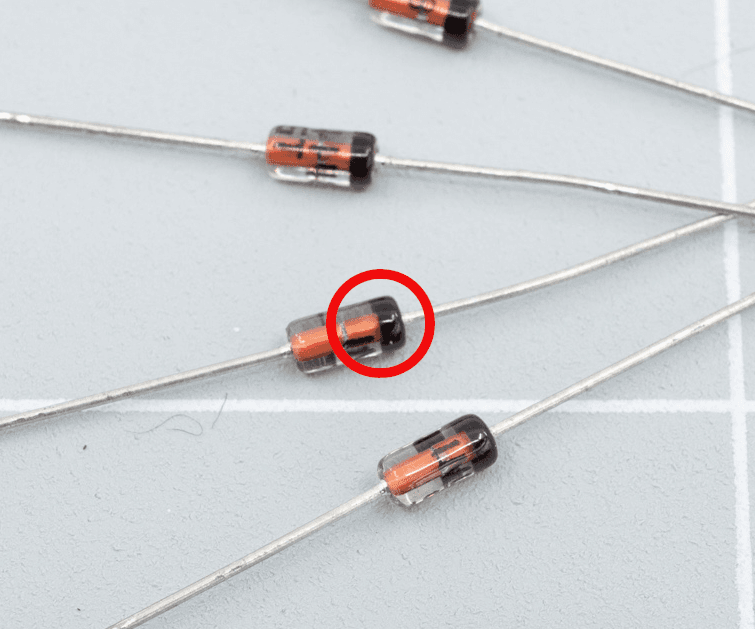
The black line on a through-hole diode hints at its intended orientation.
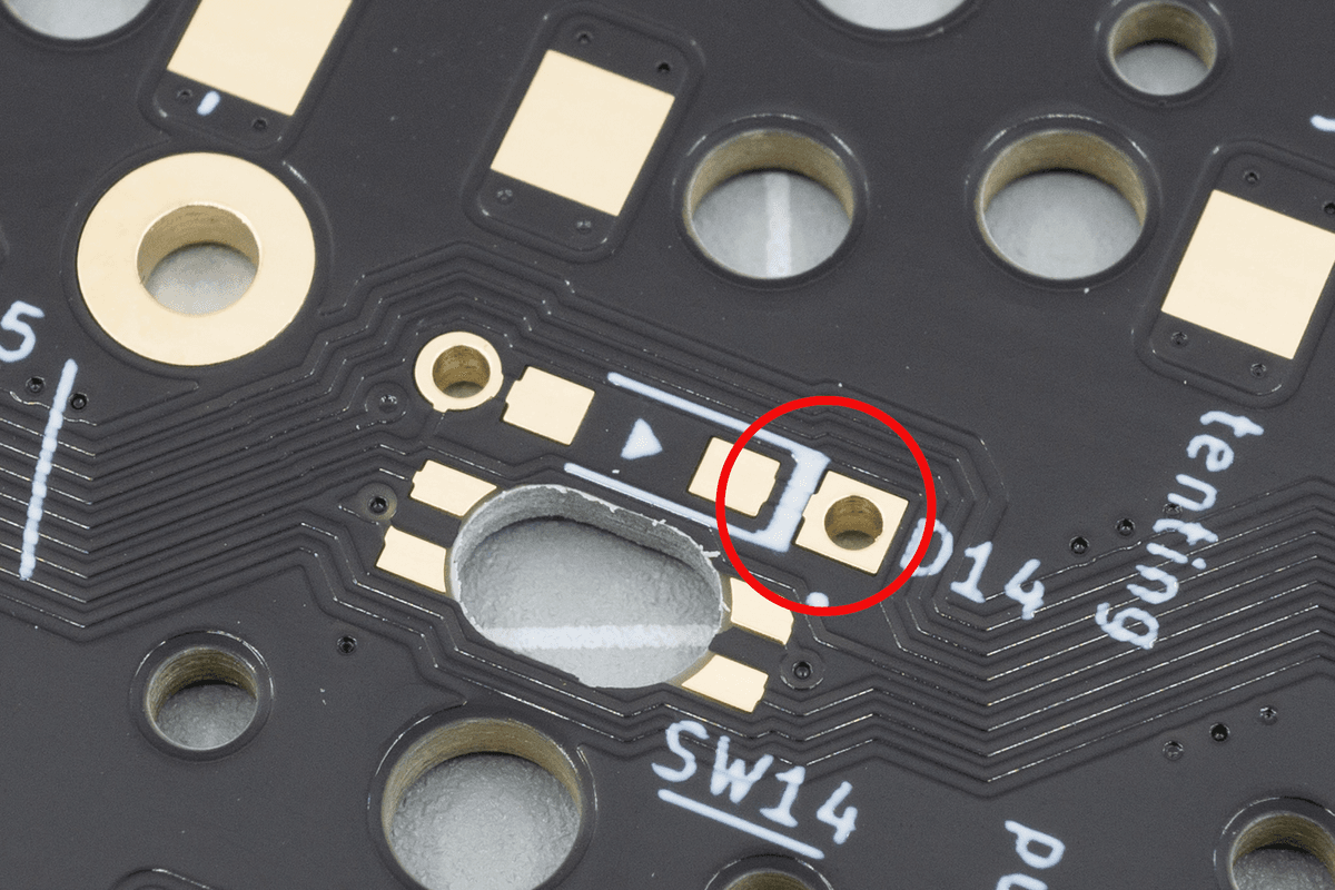
The thick white line on the PCB, next to the square pad, is where you'll also place the corresponding black line of the diode.
Start by bending the diodes. You can use a special tool for it, called a lead bender, but you can also stack some layers of your case together and bend them using those. The distance between the legs of the diode should be around 6.5mm. It doesn’t have to get that precise: as long as the general shape is right, the legs will correct themselves a little when you push the diode through the holes on the PCB.
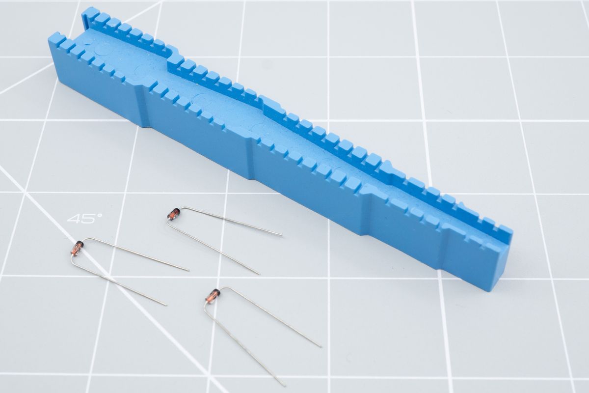
There exist special "lead bender" tools, but using the acrylic bottom plate or even just pliers works well too.
Face the PCB with its bottom side toward you, and slide the diode legs through the holes.
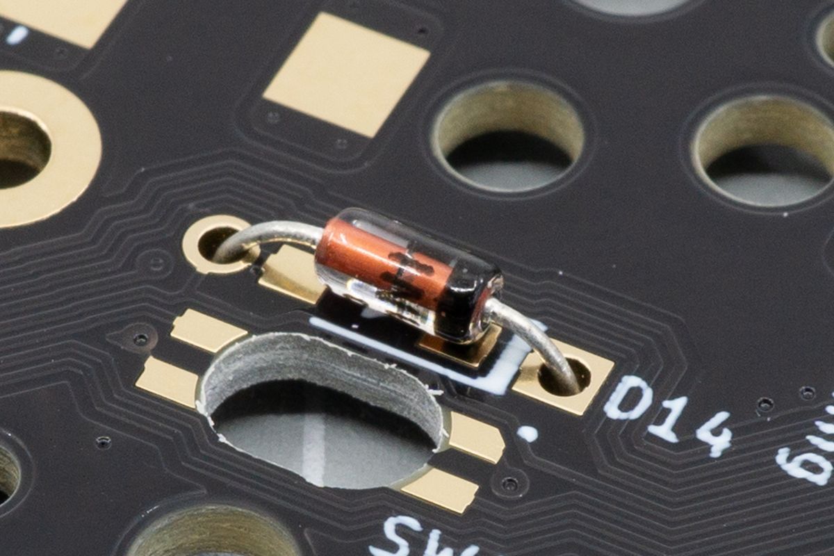
The correct placement of a through-hole diode.
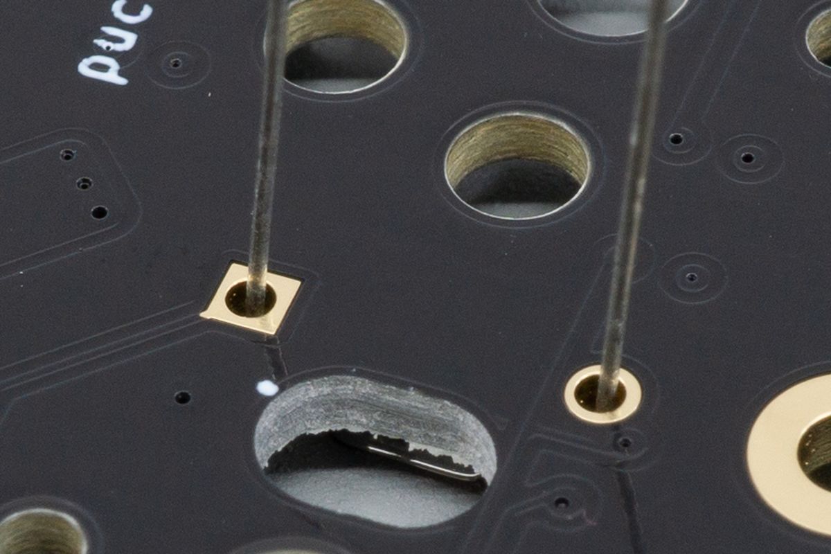
The leads of a through-hole diode sticking out of the top side of the PCB.
You can bend the legs on the top side of the PCB so the diodes will stay in place while you install them. It is usually fastest to insert all diodes in place before soldering.
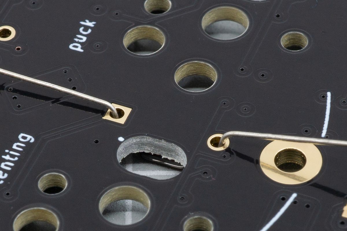
Bending the leads can help keep the diode in place while soldering.
With all the diodes in place, look through all of them one more time to verify they are oriented correctly. If the line doesn’t match up with the square pad, take the diode out and place it back in correctly.
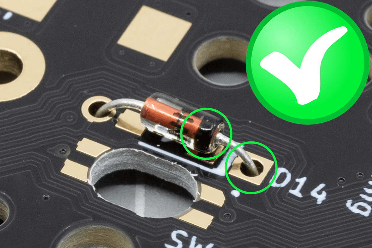
Double check: the black line of the diode faces toward the square pad and the thick white line of the PCB.
You can solder the diodes either from the top or bottom side. Soldering from the top (switch side, first image) is a little easier, while soldering from the bottom (diode side, second image) makes you able to snip the legs off a little bit flusher, which is only useful when using Choc low profile switches without hotswap sockets in combination with an acrylic plate. Whew!
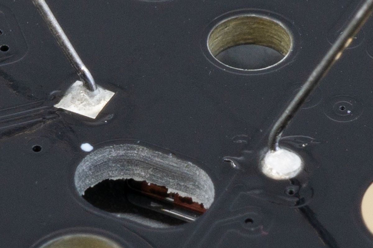
You can solder the leads from the top side of the keyboard.
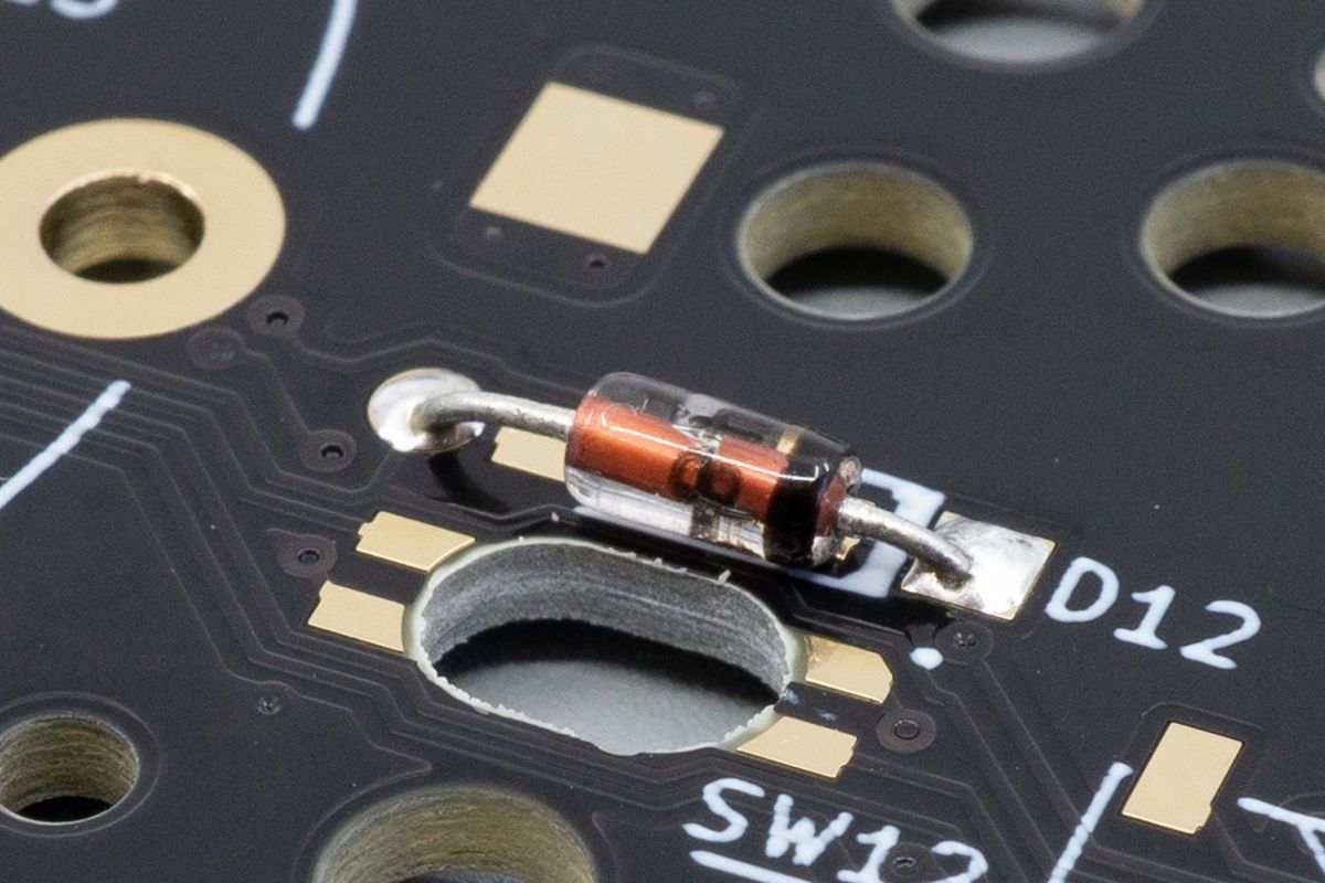
You can solder the leads from the bottom side of the keyboard, too, which is particularly helpful when using Kailh Choc low profile switches.
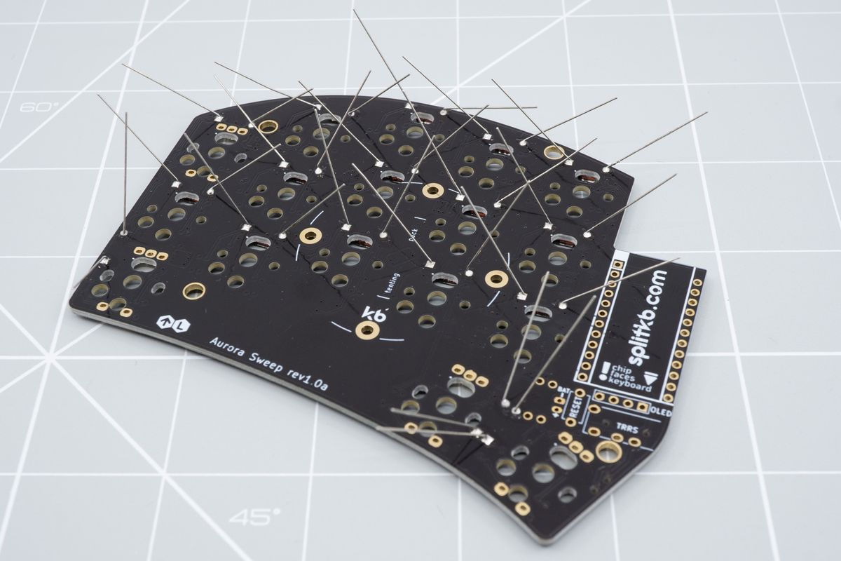
Here are all the diodes soldered from the top side of the keyboard.
After soldering the diodes, clip off the diode legs from the top side of the PCB. Hold the leg with one hand while you clip it with the other - you don't want a rogue leg flying into your eyes!
If you’re planning on socketing the microcontrollers, you might want to save the clipped off legs to use them as pins later.
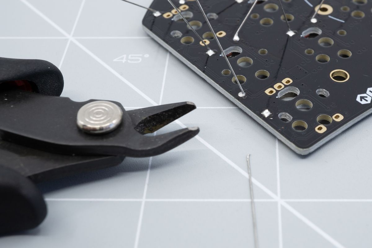
A flush cutter helps to trim the leads down flush with the PCB. You can also use cutting pliers, but the cut won't be as clean.
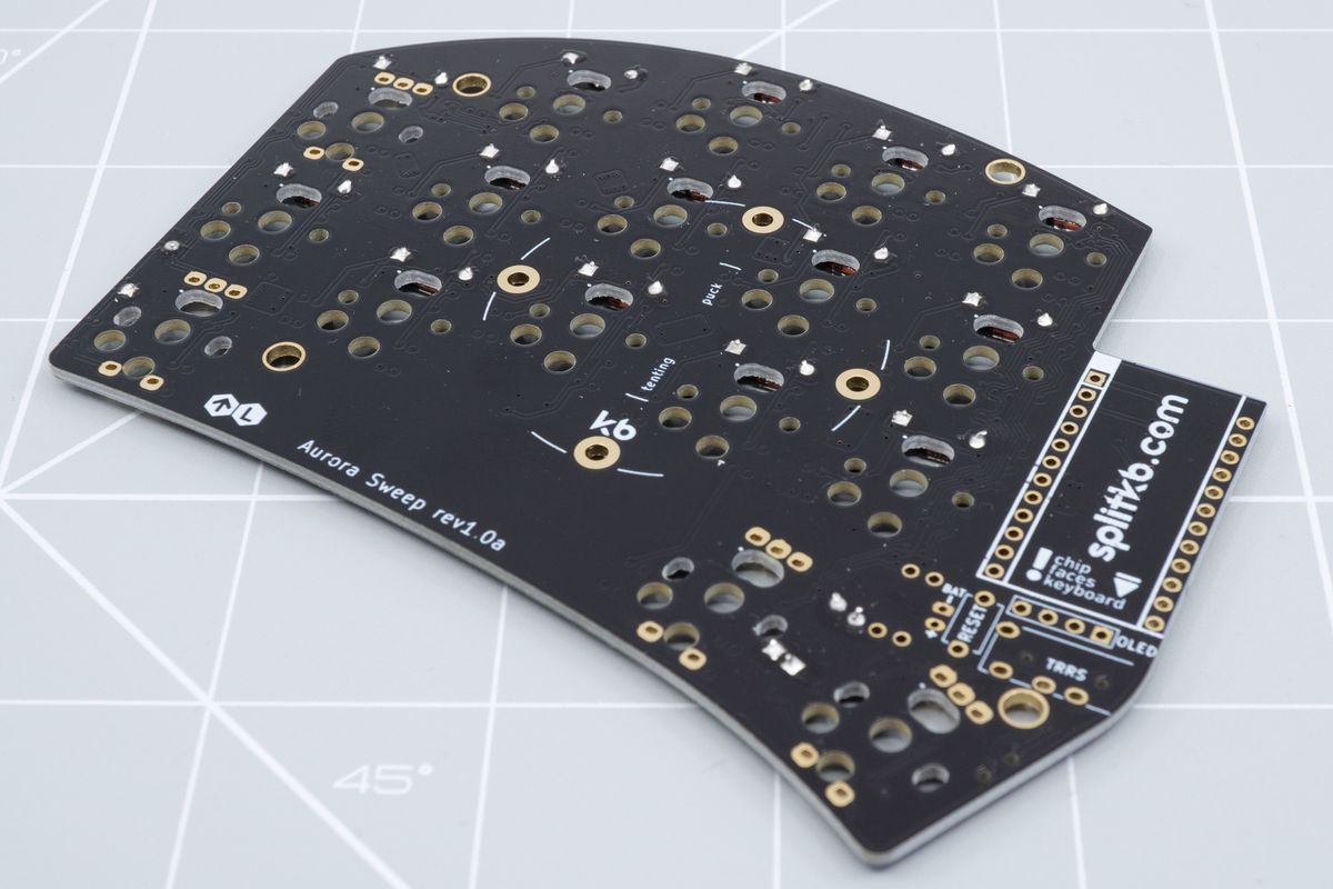
The top of the PCB after making the cuts. If you solder the leads from the bottom side, you'll be able to get the cuts much more flush than shown here.
SMD diodes
If you’re using through-hole diodes, please skip to the through-hole diodes section on this page.
The diodes positions are usually all placed next to switches, all oriented the same way where possible. They’ll be marked with a D followed by a number, like D14.
Start by familiarizing yourself with their orientation. On SMD diodes, there’ll be a gray or white line on the body of the diode which will need to match up with the square hole and the thick white line on the PCB.
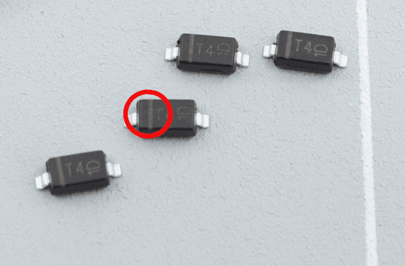
The lighter grey line hints at the diode's intended orientation.

The thick white line on the PCB, next to the square pad, is where you'll also place the corresponding gray line of the diode.
Face the PCB with its bottom side toward you, and solder some tin on one of the two rectangular pads on the diode footprint. Leave the pads with holes alone - you won’t need them for SMD diodes.
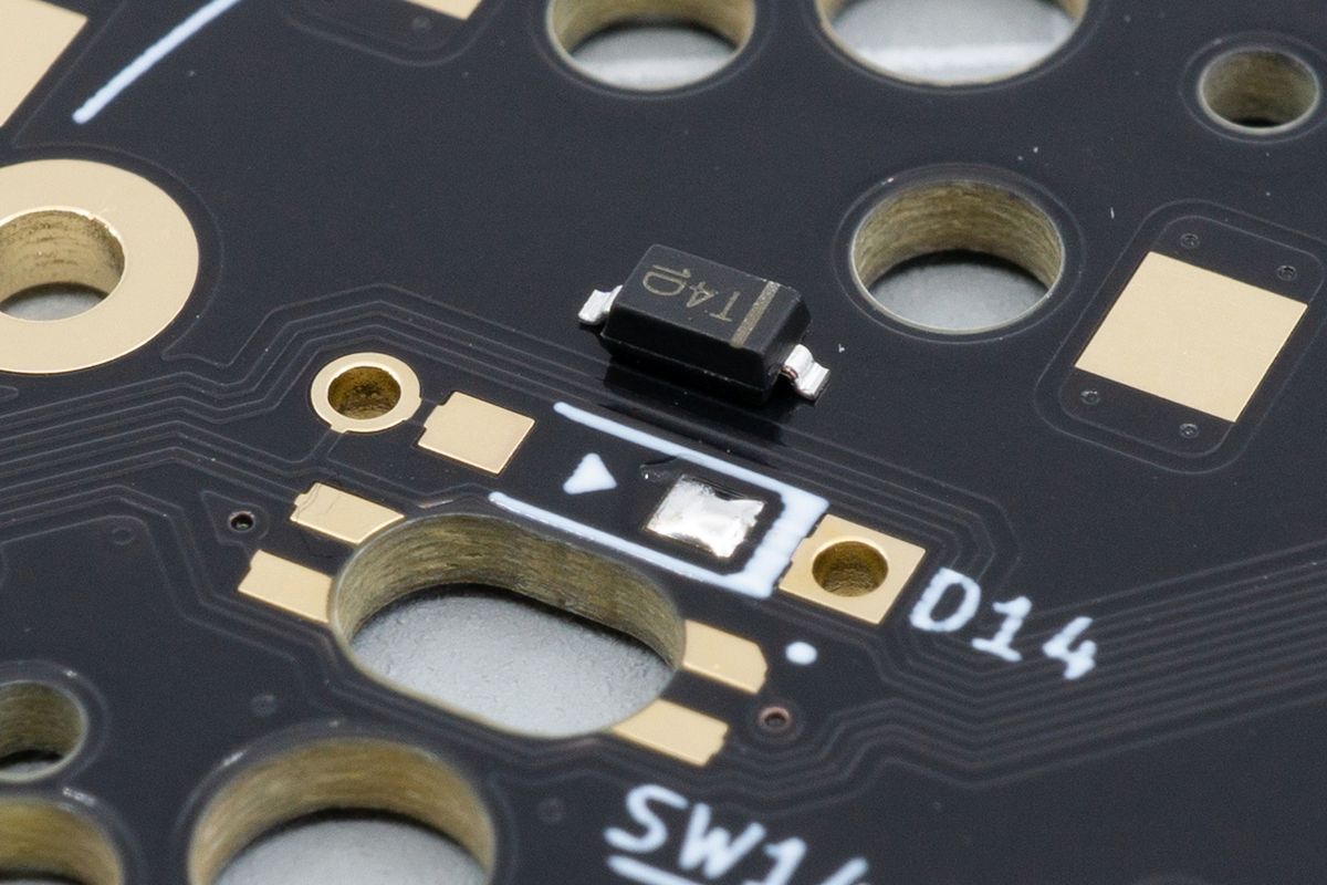
Applying some tin to one pad ahead of time makes it much easier to align the diode with the pad.
Grab a diode using tweezers in one hand, and use your soldering iron with your other hand. Move the diode next to a pad you just soldered, and heat up the solder until it melts.
Then, move the diode in place, touching both the diode leg and the pad with your soldering iron until you notice a solder joint form — this usually only takes a second or two.
Remove the soldering iron, wait until the solder joint solidifies. Then release the tweezers, and repeat this process for all of the diodes.
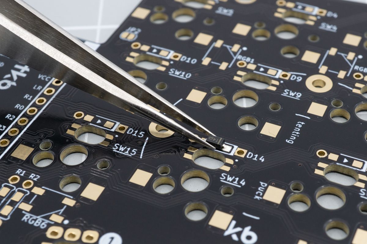
Using tweezers in one hand, move the diode in place. Using the other hand, you can then melt the solder and finalise the diode placement by nudging it around.
Solder the other joint. This one should go a lot easier as the first one is already holding the diode in place, so you don't need to use tweezers anymore.
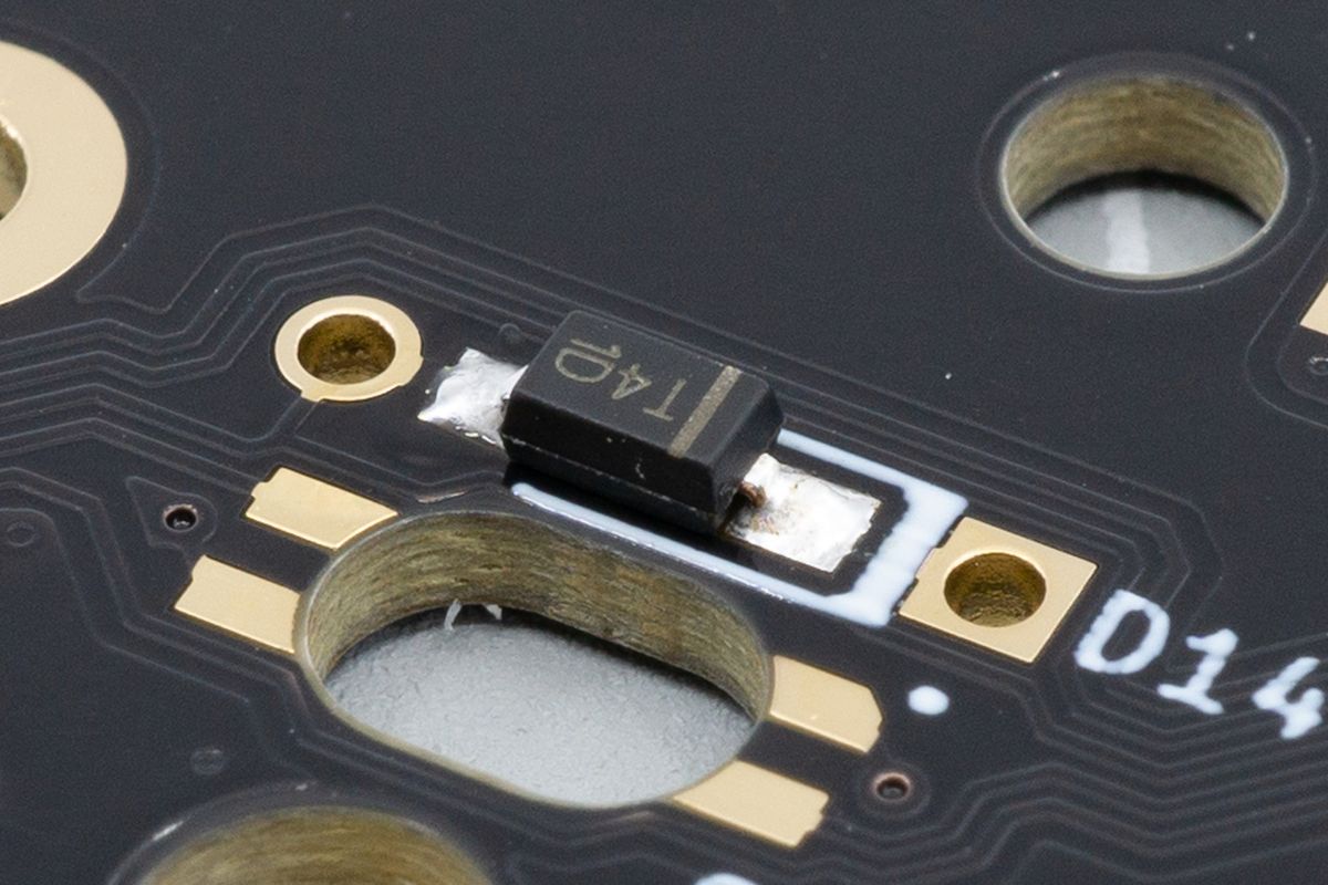
With the diode in place, we've now soldered the remaining joint.
Verify that you soldered all diodes in the correct orientation.
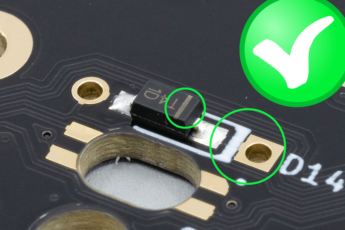
Just to be sure, double-check that the line matches up with the square pad.
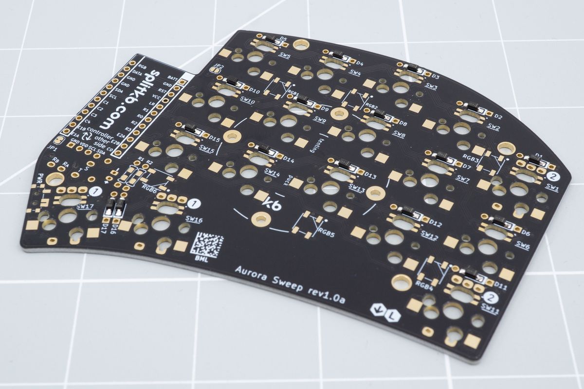
The bottom of the keyboard, showing all the assembled SMD diodes.
Known issues
Check on the issues in our kits that we know about.
Per-key RGB
Light coming up through your keycaps. Learn how to solder per-key RGB LEDs.

