Display module
Setting the VIK voltage selector
For this module you won't need to touch the VIK voltage selector switch, it can be on either 5V or NC. The 5V is not connected on the module.
How to install the module
You will need your keyboard, the display module, the flat cable, two screws and the included 1.5mm allen key. You will also need a non conductive tool to open and close the VIK connector. This can be a spudger, guitar pick, plastic screwdriver, your fingernail or something similar.
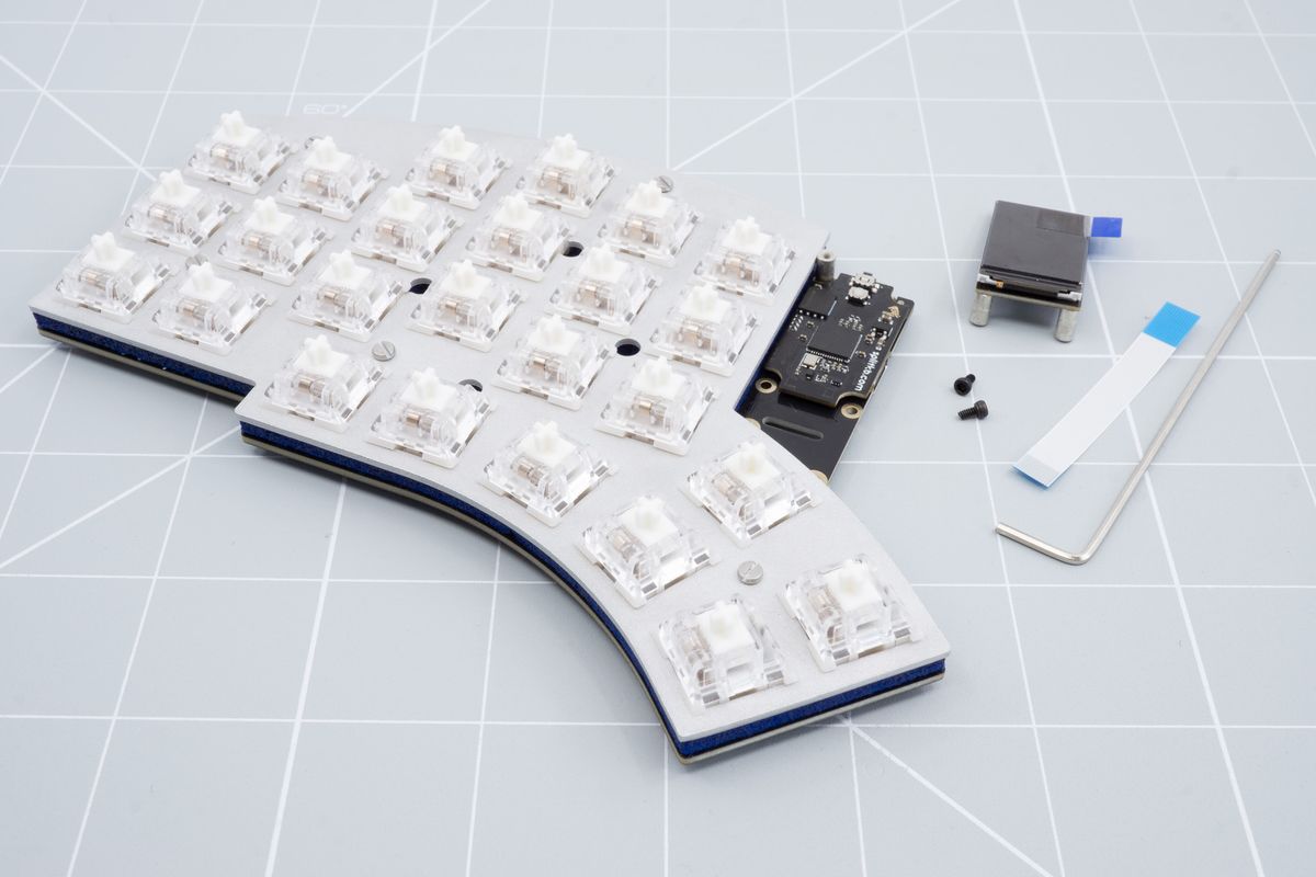
The keyboard, the display module, the flat cable, two screws and the included 1.5mm allen key.
Start by lifting up the gray little tab of the VIK connector on the module with the non conductive tool.
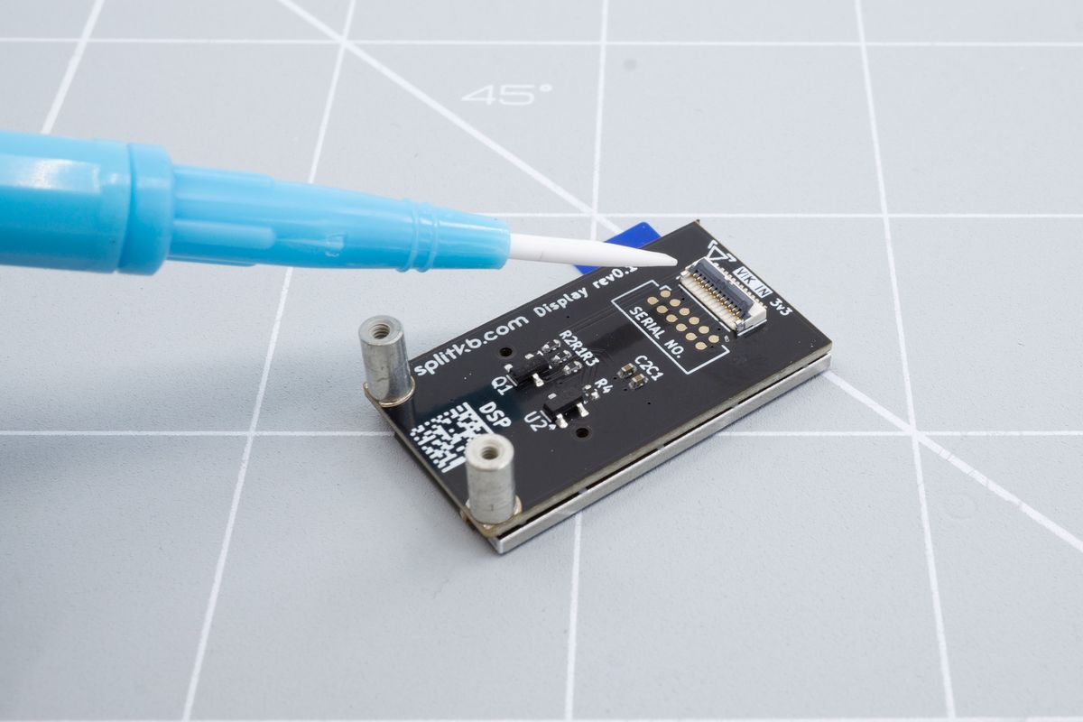
Lifting the tab on the module.
Insert the flat cable with the blue part sticking up. Push the cable in as far as possible in to the connector.
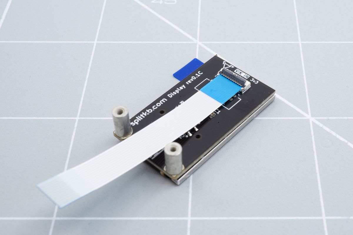
Inserting the flat cable.
Lower the tab back down with the non conductive tool. You can lightly pull on the cable to see if it's in securely.
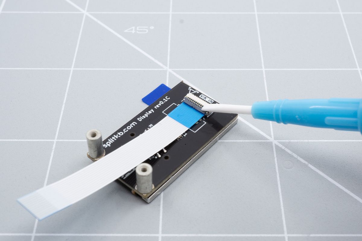
Lowering the tab back down.
Now position the module next to the keyboard.
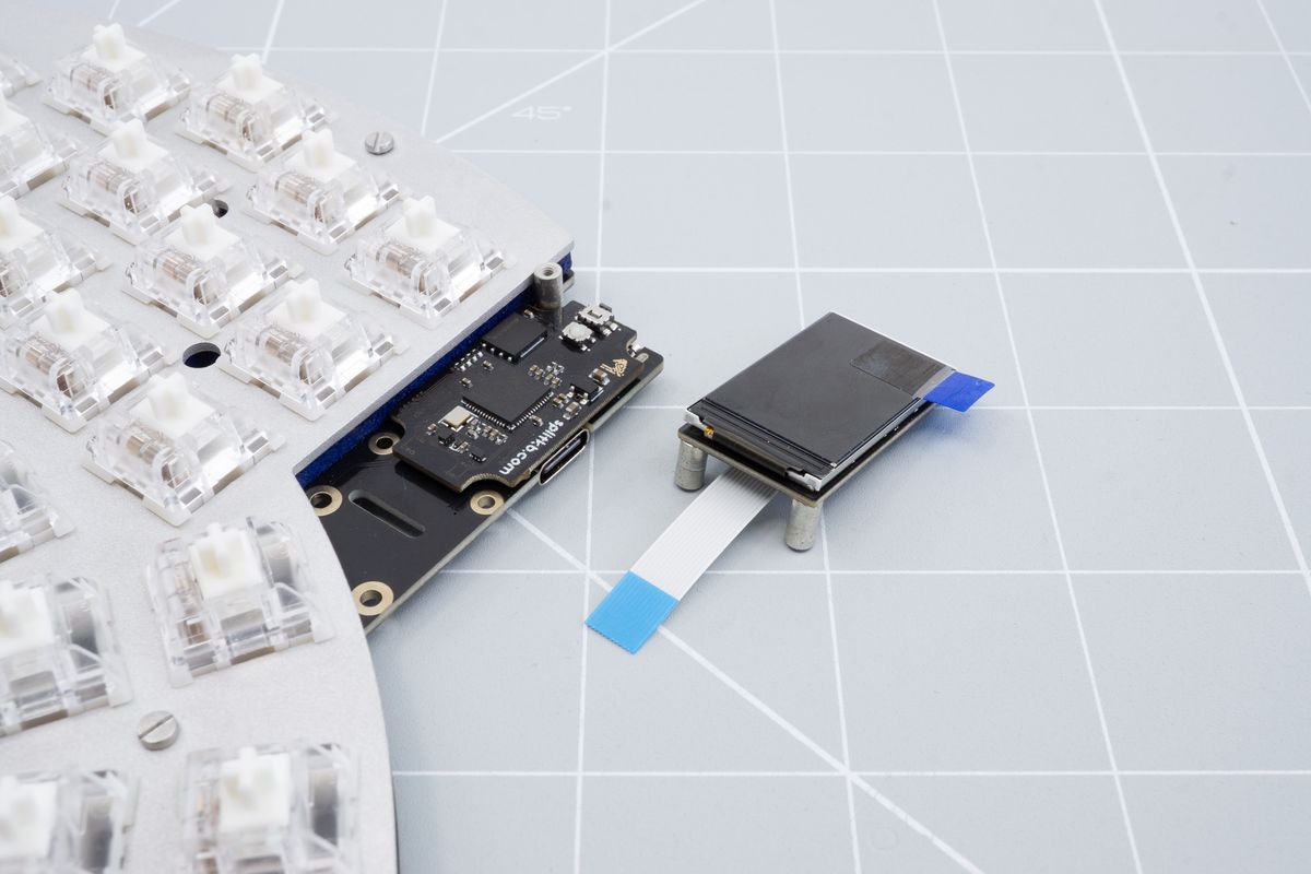
Positioning the module.
Insert the cable through the hole in the keyboard and push it through all the way until the module roughly lines up with the screw holes.
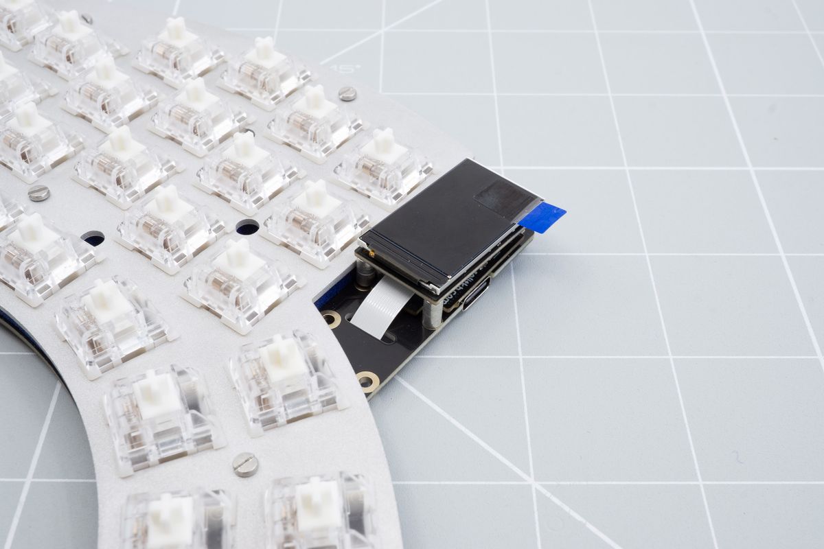
Module in the correct position.
Rotate your keyboard and screw in the module using the included screws and the 1.5mm allen key.
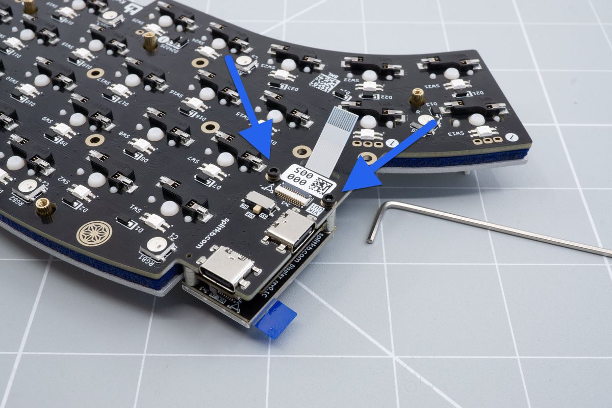
Screwing down the module.
Now lift the tab up from the VIK connector on the keyboard using the non conductive tool.
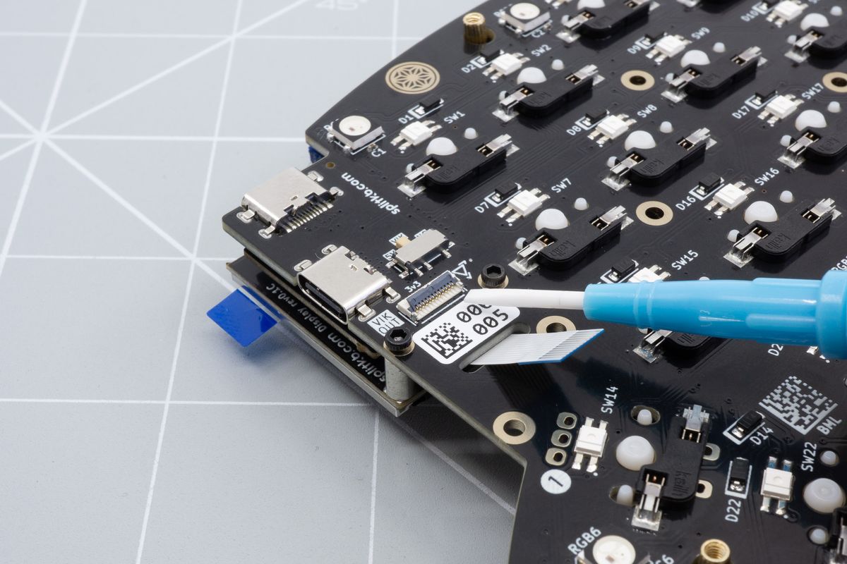
Lifting the tab up on the keyboard.
Now insert the cable. The easiest way is to push down on the cable with your finger and carefully push it in to the connector until you can't push it in any further.
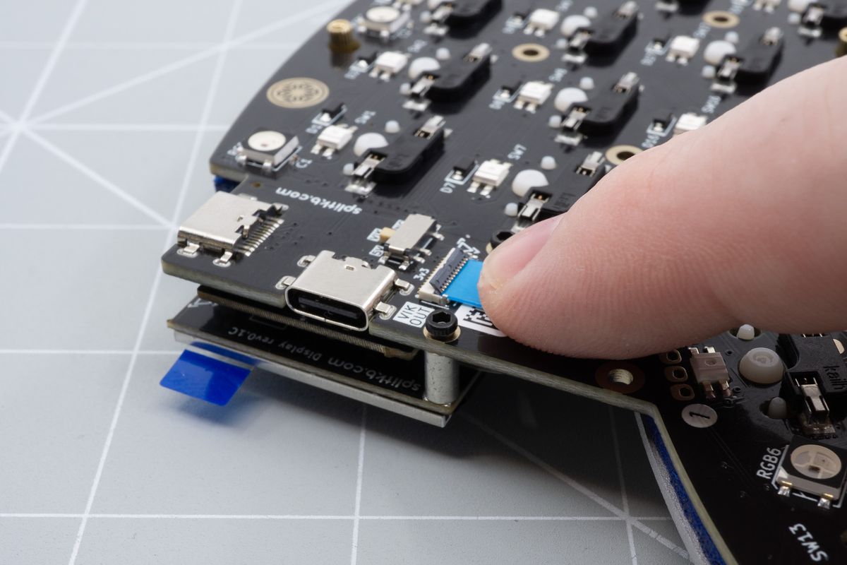
Pushing in the cable with your finger.
Lower the tab back down with the non conductive tool.
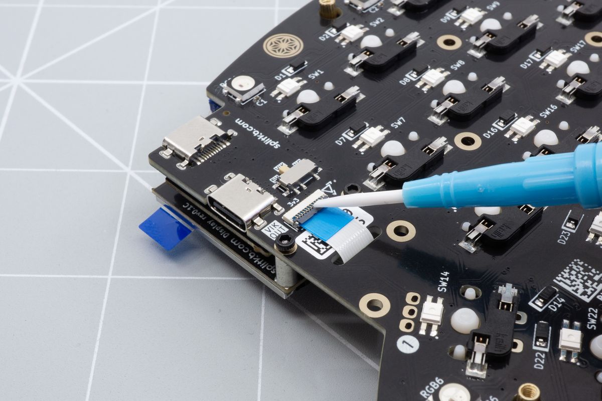
Lowering the tab back down.
You've now successfully installed the display module! You can now continue with the build guide.
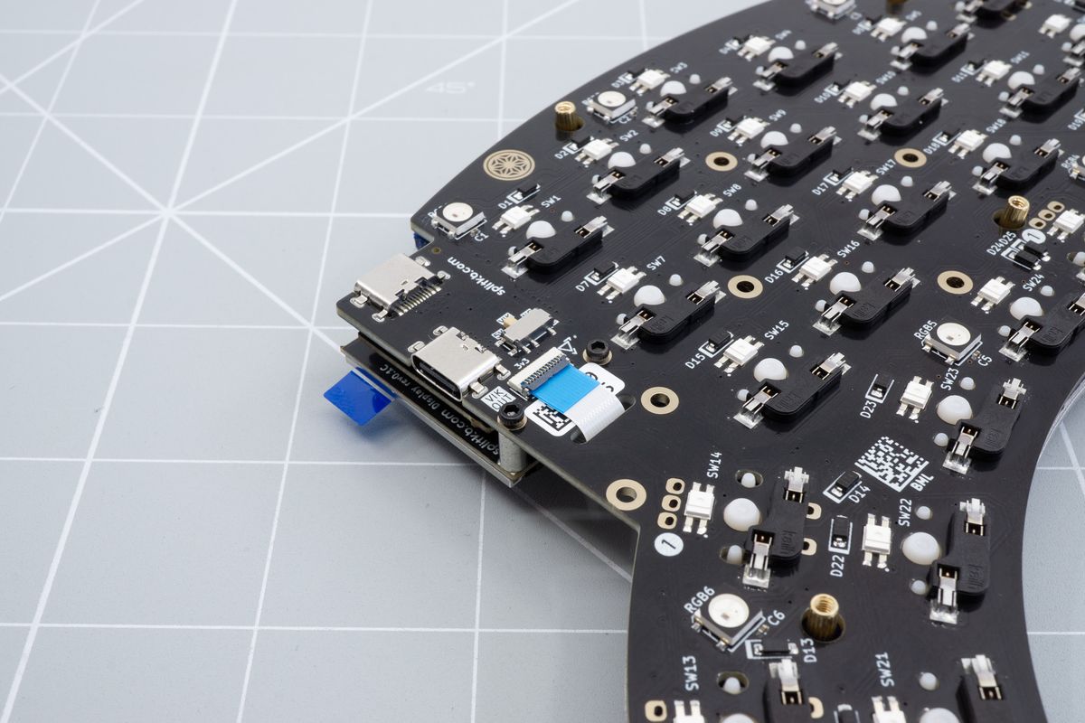
Installed module.
Using the module
Using the module is as easy as just plugging it in with the correct firmware installed on your keyboard.
If you only have one display on your split keyboard set you will always see the screen with information about which layer you're on and the status of the num lock, scroll lock and caps lock.
If you have two displays, the slave side of the keyboard will show conway's game of life on it. Which will spawn new cells in random colors when you type on your keyboard!
Within vial you can also assign buttons to change the brightness of the screens using the backlight feature. (BL + and BL -)
Customizing the behavior
To customize your display you will need to add some files to your keymap. A complete example can be found in the examples directory in our qmk_userspace fork. The files in this example can be added to your keymap folder. Some more simple examples can be found below.
Within the example you can see how a display code should be built up. The functions used here are more thoroughly explained in the Quantum Painter API documentation from QMK. Because we added some extra hooks which you can read more about here, any actual display initialization is already done so you don't have to worry about that. We make use of the surface feature of quantum painter. This makes it so it only draws changed parts of the display. Which is why we use the qp_surface_draw feature at the end of the code.
There are some quirks when using Quantum Painter which we noticed while creating our firmware which can help if you want to create your own display behavior.
- Font size is determined when generating the file using the CLI.
- You need to generate mono2 fonts if you want to recolor the font but this pretty much breaks any aliased font. So a pixel font is recommended.
- Using pixel fonts you can scale them 2 or 4 times larger but somehow they break at a certain point when going too large. We fixed this by just creating images of the fonts and using that.
- If you want to wrap around text, you'll need to create a custom function for that.
- Drawing a full screen image can give the keyboard noticeable lag. For startup this is okay but switching images every couple of seconds could become annoying.
- This also applies for animations. Smaller size animations are fine, from testing the animations could take up around 30% of the screen and still have the keyboard be responsive but when having animations on the entire screen it can slow down the entire keyboard.
- Using large images or animations can eat up the firmware size very quickly so be aware of that.
- Our displays are 240*135 pixels.
You can also look in the users/halcyon_modules/hlc_tft_display/ folder to see how we implemented the display code.
To load new fonts or images you will need to convert them using the Quantum Painter CLI tools.
Example: draw a picture on the second display
First convert your 240*135 image to a QGF file:
qmk painter-convert-graphics -f rgb565 -i my_image.png
Copy the generated files to your keymap.
In your rules.mk add
SRC += my_image.qgf.c
And in your keymap.c add:
#include "hlc_tft_display/hlc_tft_display.h"
#include "qp_surface.h"
#include "my_image.qgf.h"

static painter_image_handle_t my_image;

painter_device_t lcd;
painter_device_t lcd_surface;

bool module_post_init_user(void) {
    return false;
}

bool display_module_housekeeping_task_user(bool second_display) {
    static bool display_set = false;

    if(second_display) {
        if (!display_set) {
            my_image = qp_load_image_mem(gfx_my_image); // Get the `gfx_my_image` from the `my_image.qgf.h` file
            qp_drawimage(lcd_surface, 0, 0, my_image);
        }
    }

    if(!second_display) {
        // Re-use the function to display layers and status
        update_display();
    }

    qp_surface_draw(lcd_surface, lcd, 0, 0, 0);

    return false;
}
Example: write some colorful text on the display
First convert your font to an image file:
qmk painter-make-font-image -s size_of_font -o ./ -f my_font.ttf
Now convert the generated font image
qmk painter-convert-font-image -f mono2 -i my_font.png
In your rules.mk add
SRC += my_font.qff.c
And in your keymap.c add:
#include "hlc_tft_display/hlc_tft_display.h"
#include "qp_surface.h"
#include "my_font.qff.h"

static painter_font_handle_t my_font;

painter_device_t lcd;
painter_device_t lcd_surface;

bool module_post_init_user(void) {
    my_font = qp_load_font_mem(font_my_font);
    static const char *text = "Hello from SplitKB!";
    int16_t width = qp_textwidth(my_font, text);
    qp_drawtext_recolor(lcd_surface, (LCD_WIDTH - width), (LCD_HEIGHT - my_font->line_height), my_font, text, HSV_BLUE, HSV_BLACK);
    qp_surface_draw(lcd_surface, lcd, 0, 0, 0);
    return false;
}

bool display_module_housekeeping_task_user(bool second_display) {
    return false;
}
Modules
Installing and using your Halcyon modules.
Encoder module
How to install and use the Encoder module.

