JST jacks
You should perform this step if you are building a wireless keyboard, are using the wireless expansion bundle and if your kit supports the JST jack. If not, you can go to the next step using the button below.

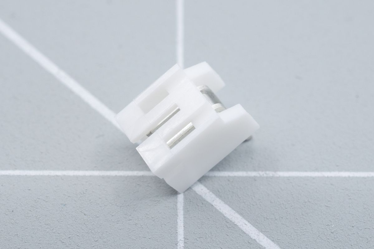
The top side of a JST jack.
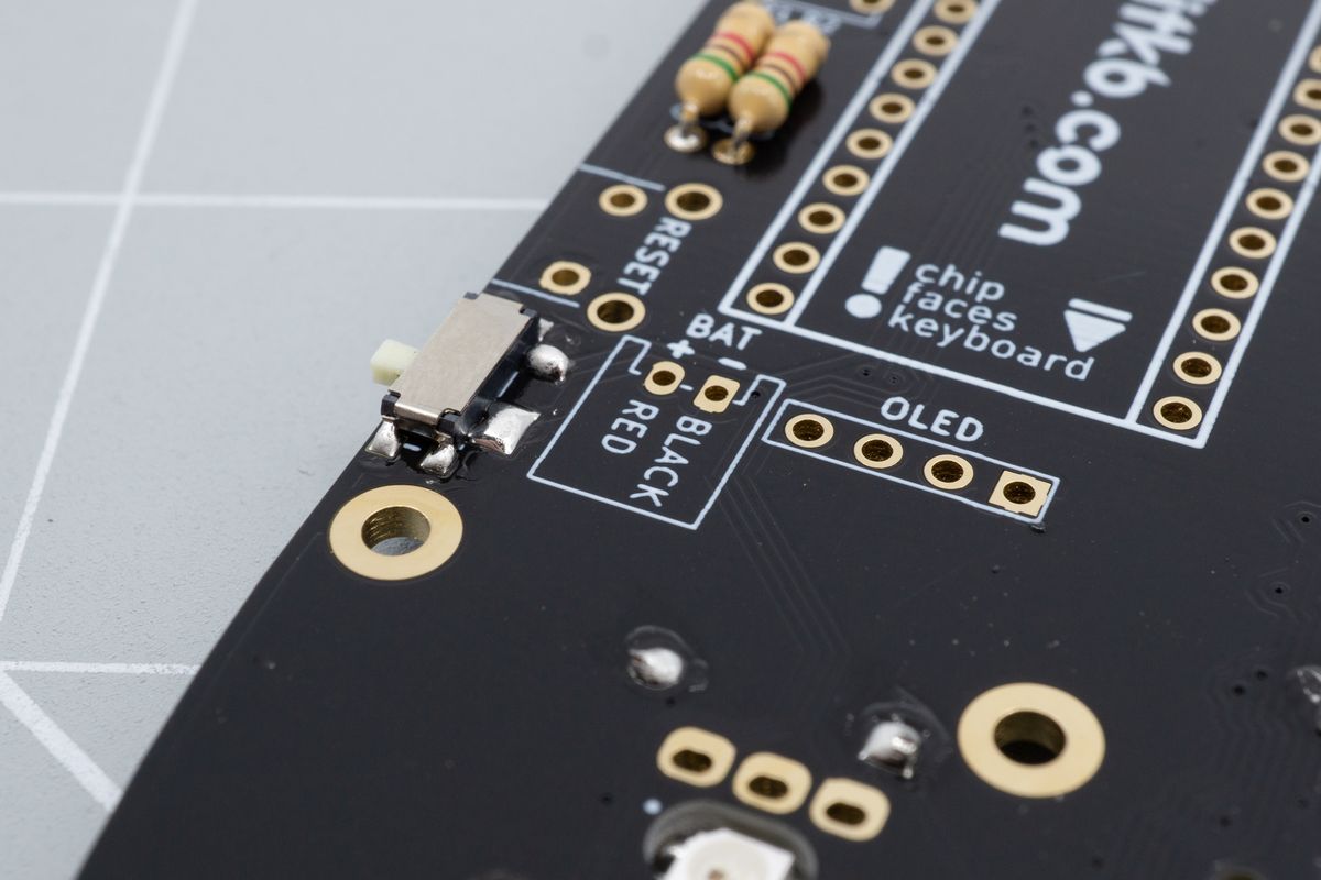
Locate the outline for the JST jack. It will be labelled "BAT" and it is usually placed near the microcontroller on the top side of the board.

The battery footprint. The white rectangular outline shows it's compatible with the JST jack. If there's no rectangle, then you should skip this section and manually connect the battery in a later step.
Insert the jack. Its legs will probably hold it in place when you flip the board over.
Can't get the jack to stay in? You can use a piece of tape to fix it in place. The kind of tape doesn't matter, as it won't get hot during soldering.

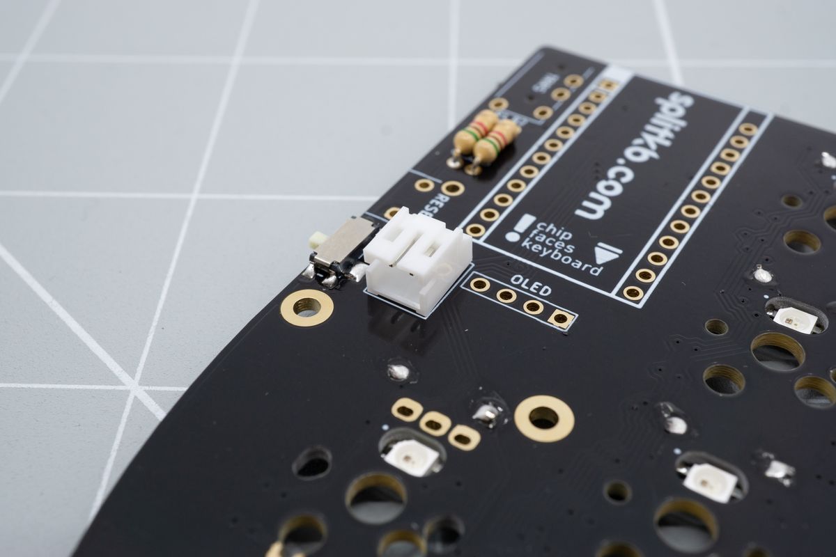
A JST jack placed on the top side of the keyboard, on top of the white outline.
Solder both legs, and repeat the process for the other half

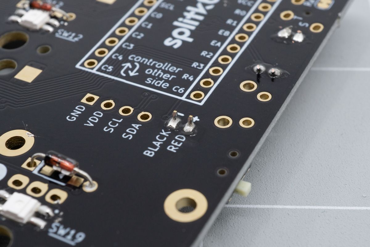
A soldered JST jack, looking from the bottom side of the keyboard. You won't need to clip the leads off.
Resistors
Resistors pull up the I2C connection, enabling I2C accessories to work correctly. Let's solder them!
Reset buttons
Using a reset button, you can reboot your keyboard and flash new firmware to it.

