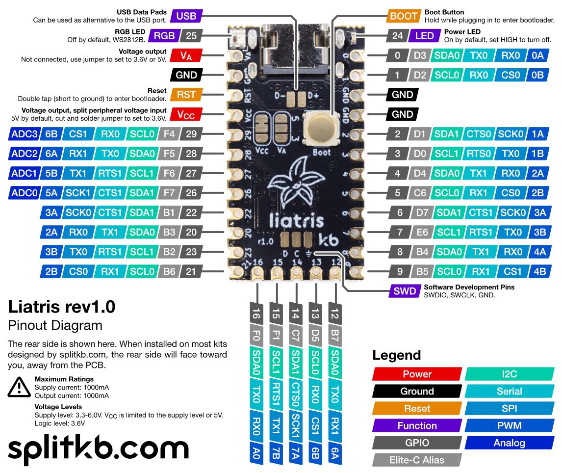
Pinout diagram
With this pinout diagram, you'll be able to tell more easily which functions belong to which pins on your Liatris. It's often used when writing your own firmware from scratch, or while developing a new keyboard or project.

Liatris rev1.0 pinout diagram.
RP2040
For more information on the functionality of individual pins, please refer to the RP2040 Datasheet. It'll also contain information on various limits and other capabilities - the Liatris is essentially an RP2040 dev board, after all.
Reset
The reset pin is internally wired to RUN, while the boot button pulls down QSPI_CS. The reset pin uses QMK's double-tap reset functionality, whereas the boot button uses the RP2040 native way to enter the bootloader.
On first use, the Liatris should enter the bootloader mode automatically, as its memory will have been emptied at the factory during the quality assurance process. On subsequent use, you'll be able to use either the boot button or the reset pin. When using firmware different from QMK, you may not be able to use the reset pin - the boot button is always available as a fallback.
Flashing
Steps to flash your Liatris controller.
Power LED
Turn off your Liatris' power LED, or use it to display the state of your keyboard.

