About Split Keyboards - Schematics
Halcyon Ferris
What connects to what? Check out the Halcyon Ferris schematics here.
Revision 1
Every Halcyon Series keyboard follows the Halcyon Controller specification. If the keyboard has multiple versions, such as a version for MX switches and one for Kailh Choc low profile switches, the pins assigned will be the same for both. Please refer to that page as well as the table below to determine the pin mapping:
| Functional pin | Keyboard left side | Keyboard right side |
|---|---|---|
| IO_01 | COL0 | COL0 |
| IO_02 | ROW3 | ROW3 |
| IO_03 | ROW2 | COL2 |
| IO_04 | COL1 | ROW0 |
| IO_05 | COL2 | ROW1 |
| IO_06 | ROW0 | ROW2 |
| IO_07 | COL3 | COL4 |
| IO_08 | COL4 | COL3 |
| IO_09 | ROW1 | COL1 |
| IO_10 | SIDE (3V3) | SIDE (GND) |
| IO_11 | Not connected | Not connected |
| IO_12 | Not connected | Not connected |
| IO_13 | Not connected | Not connected |
| IO_14 | Not connected | Not connected |
| IO_15 | Not connected | Not connected |
| IO_16 | Not connected | Not connected |
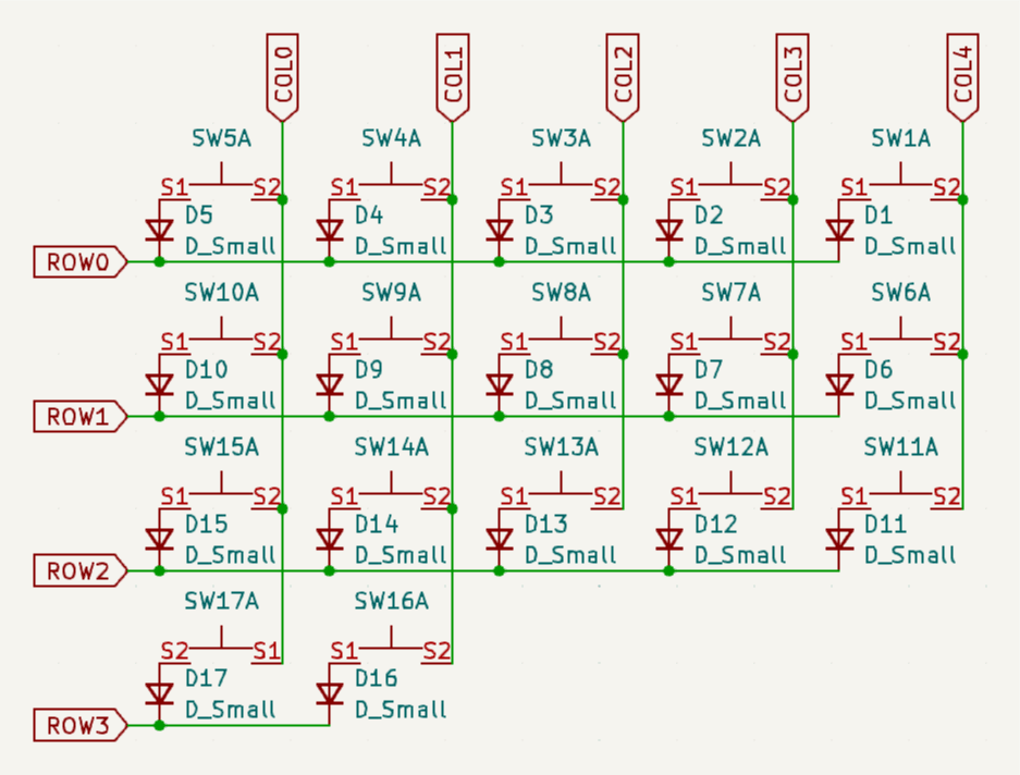
Halcyon Ferris rev1 schematics.
Questions? Help us improve!
Do you have questions after reading the documentation? Do you have feedback about this page, or about the documentation in general? Please send us an email. You can use the buttons below which will open your mail client or app with a template, or send your mail to support@splitkb.com.