What's what?
Take your kit and its components out of the packaging. We’ll go have a look at identifying the parts in your kit, and the various places they can go into and onto your PCB.
Your package might not include all parts and not every component is required to complete your build. Most optional parts can be skipped and added later, although we do recommend assembling it all at once.
The PCB
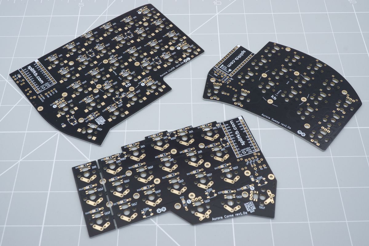
A few PCBs from Aurora Series keyboards.
The PCB forms the basis for your keyboard. PCB is an abbreviation for “printed circuit board”, and you can think of it as a fancy way to hold a bunch of wires together.
The PCB consists of various layers of material, the most important of which are the fibreglass material base and the conductive copper layers on both sides of the base. Those conductive layers ensure that electrical signals can move through your keyboard, to and from the microcontroller.
It’s unlikely but possible to damage these conductive layers while soldering. Since they’re essentially just wires, they’re easy to repair with any conductive wire as well. We don’t think that’ll be necessary during your build, though, but it’s good to know not everything is lost if it does happen.
Which side? Each PCB has a bottom side and a top side. Look for the markings in hexagons on your board: you’ll see an arrow pointing toward the top on one side, and an arrow pointing toward the bottom on the other. Similarly, each kit has two PCBs: a left side and a right side, denoted by an L and an R within a hexagon on either side. These markings are used throughout the guide to help you find where to place the components.
Diodes
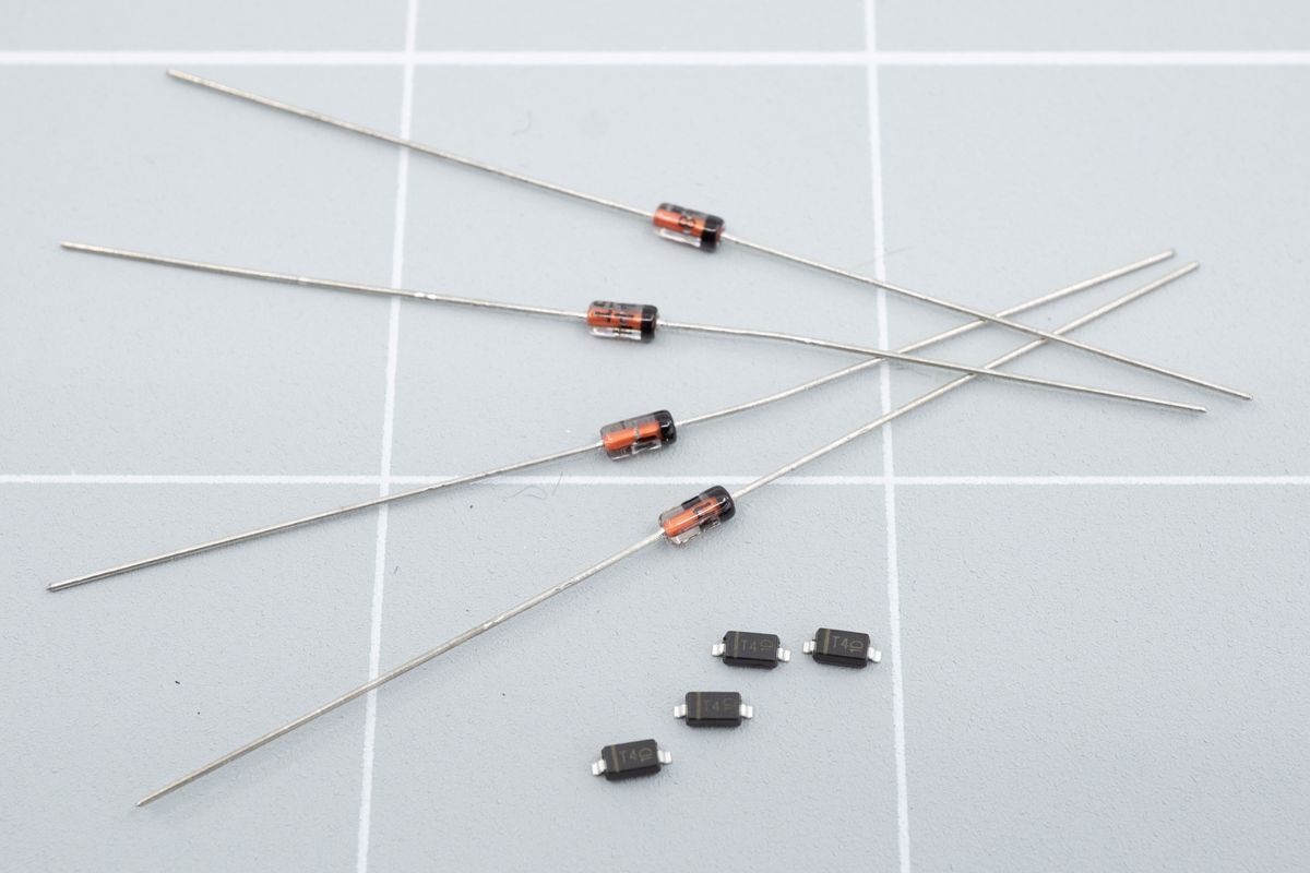
The glass beads on rods are called 'through hole' diodes, while the little black boxes are SMD diodes.
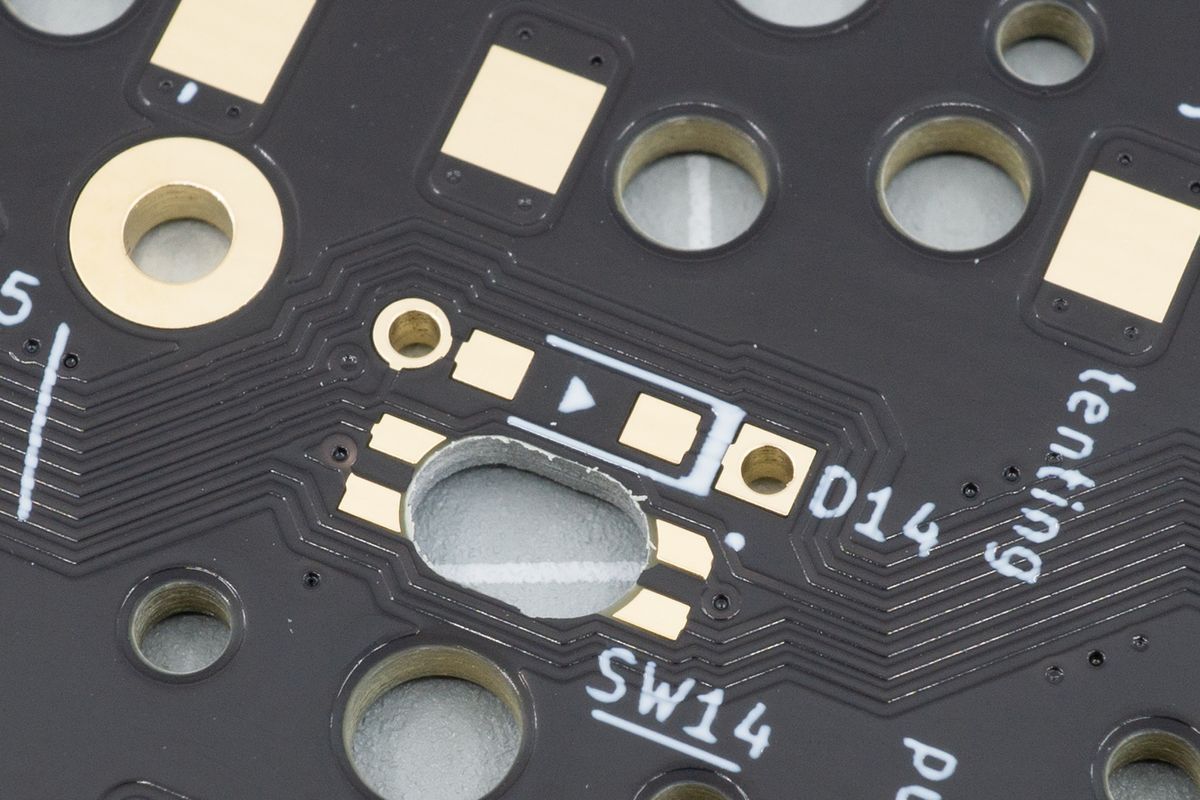
You'll solder them to this footprint, next to D14. The through hole diodes go through the holes, while the SMD diodes use the pads in the middle.
Diodes allow the flow of electricity in one way, while preventing it to move the other way. Diodes prevent ghosting in your keyboard, which is when keypresses happen while you didn’t press the keys. Diodes also allow you to enable N-key rollover, which allows you to press more than six keys at the same time.
Diodes can look like little glass beads on a piece of metal wire (called the “legs” of the component), but they can also look like a little black box with metal legs on the side. They’re both about as easy to solder, though we recommend beginners to start with the glass-looking ones.
Resistors
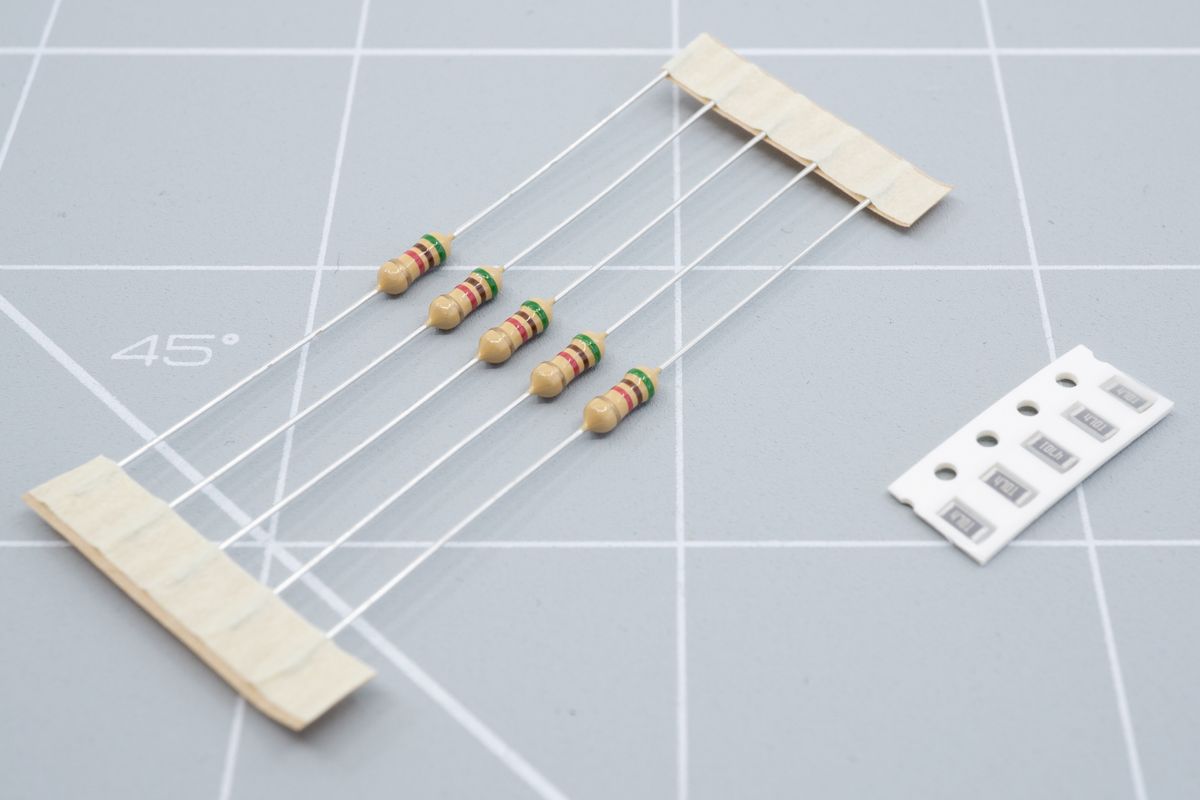
Through hole resistors on the left, and SMD resistors on the right.
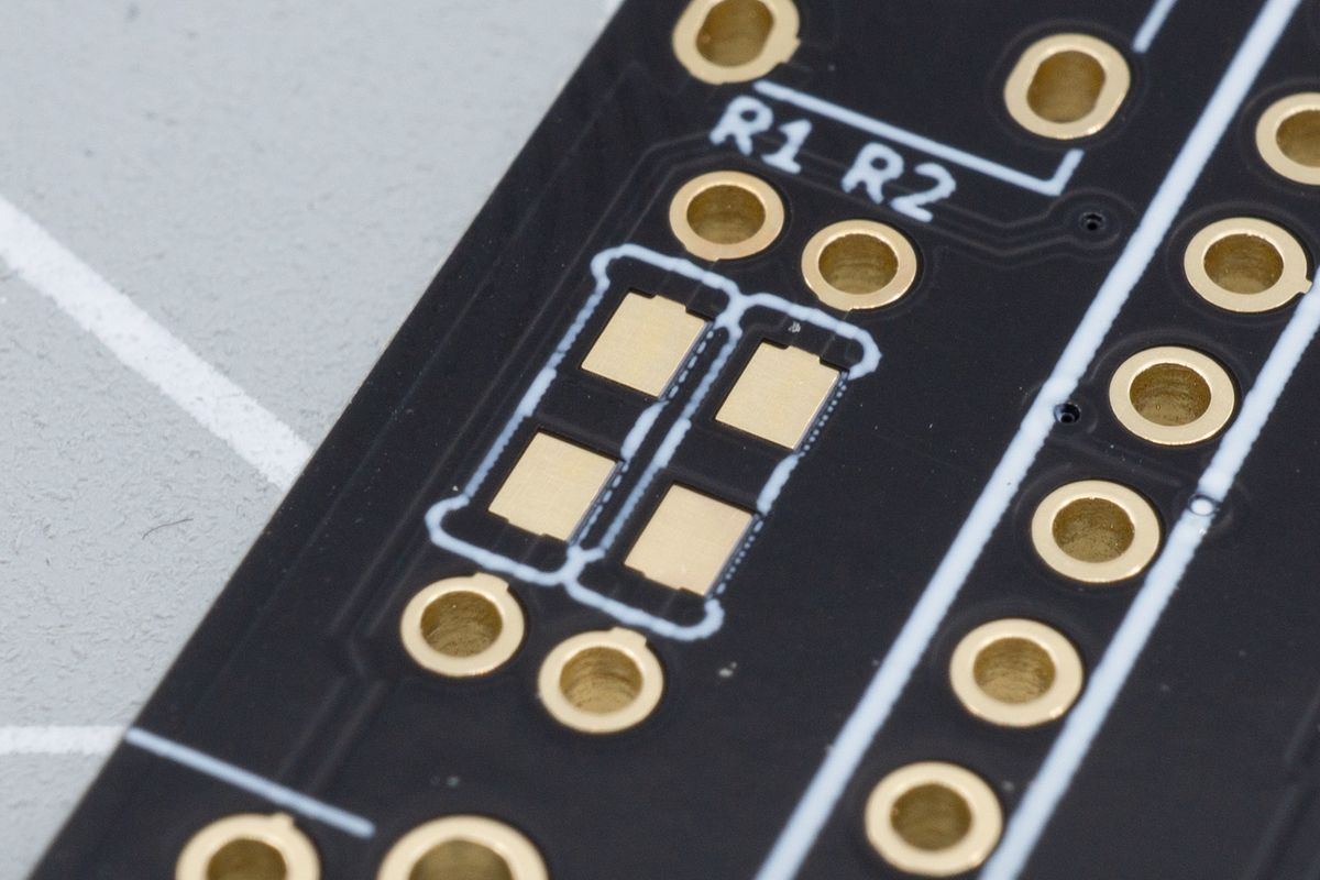
The footprint is similar to that of the diodes earlier.
Resistors provide some amount of resistance to electricity. They help direct or restrict the flow. In our kits, they help keep the signals to the OLED display high. If we wouldn’t do this, some displays might not react properly.
Backlight RGB LEDs
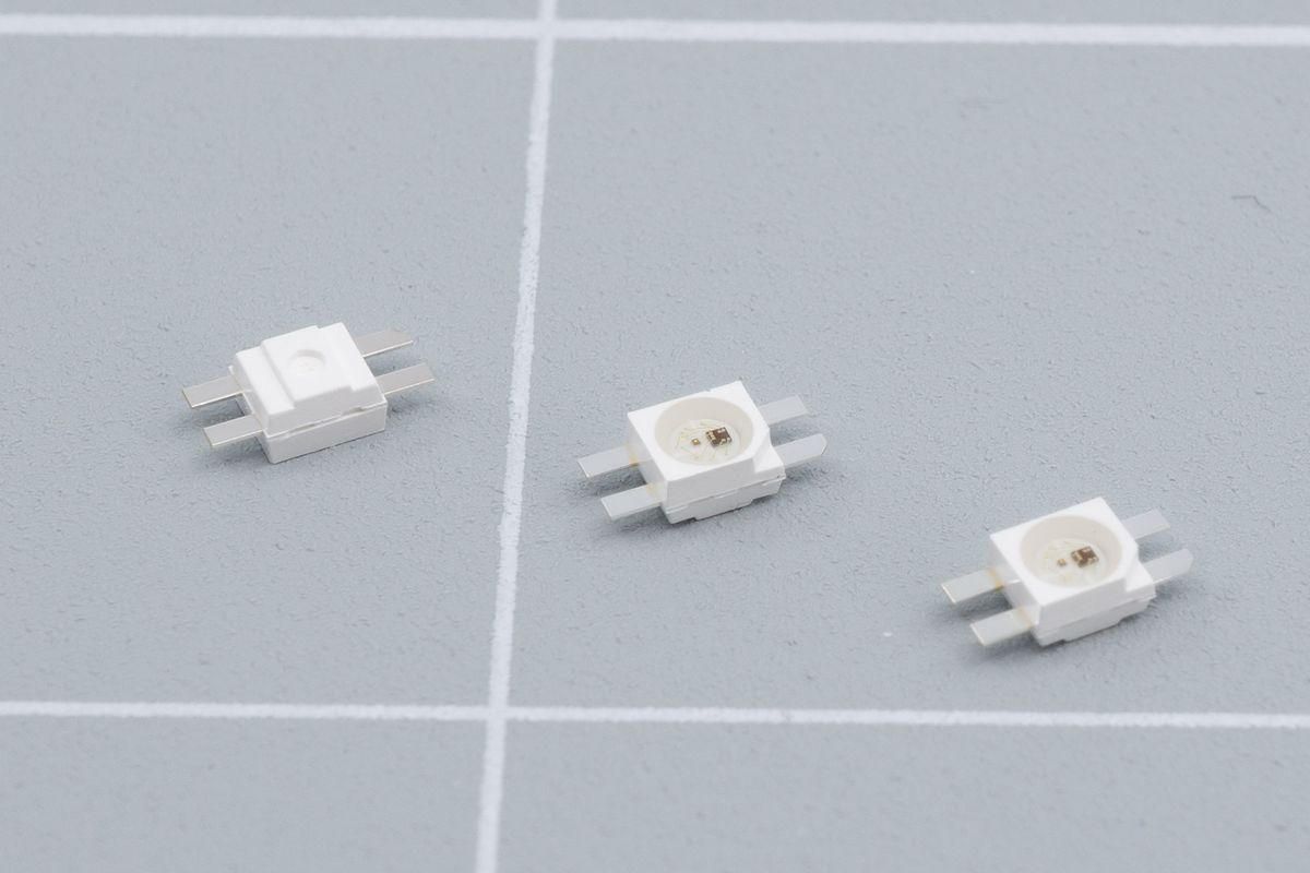
Itty bitty leggy LEDs. They have a convenient corner to mark its orientation, and the legs make them easier to solder.
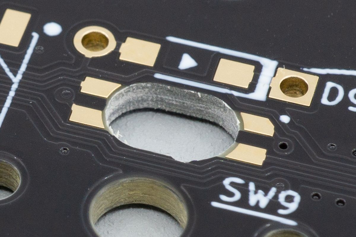
The LEDs get dropped face-down into the hole, where they then shine upward through the switches.
RGB LEDs provide colourful light. These backlight LEDs have little legs that allow them to be mounted from the back of the keyboard, shining light through your switches and maybe even through your keycaps. They’re quite small, but the legs make them easier to solder.
Underglow RGB LEDs
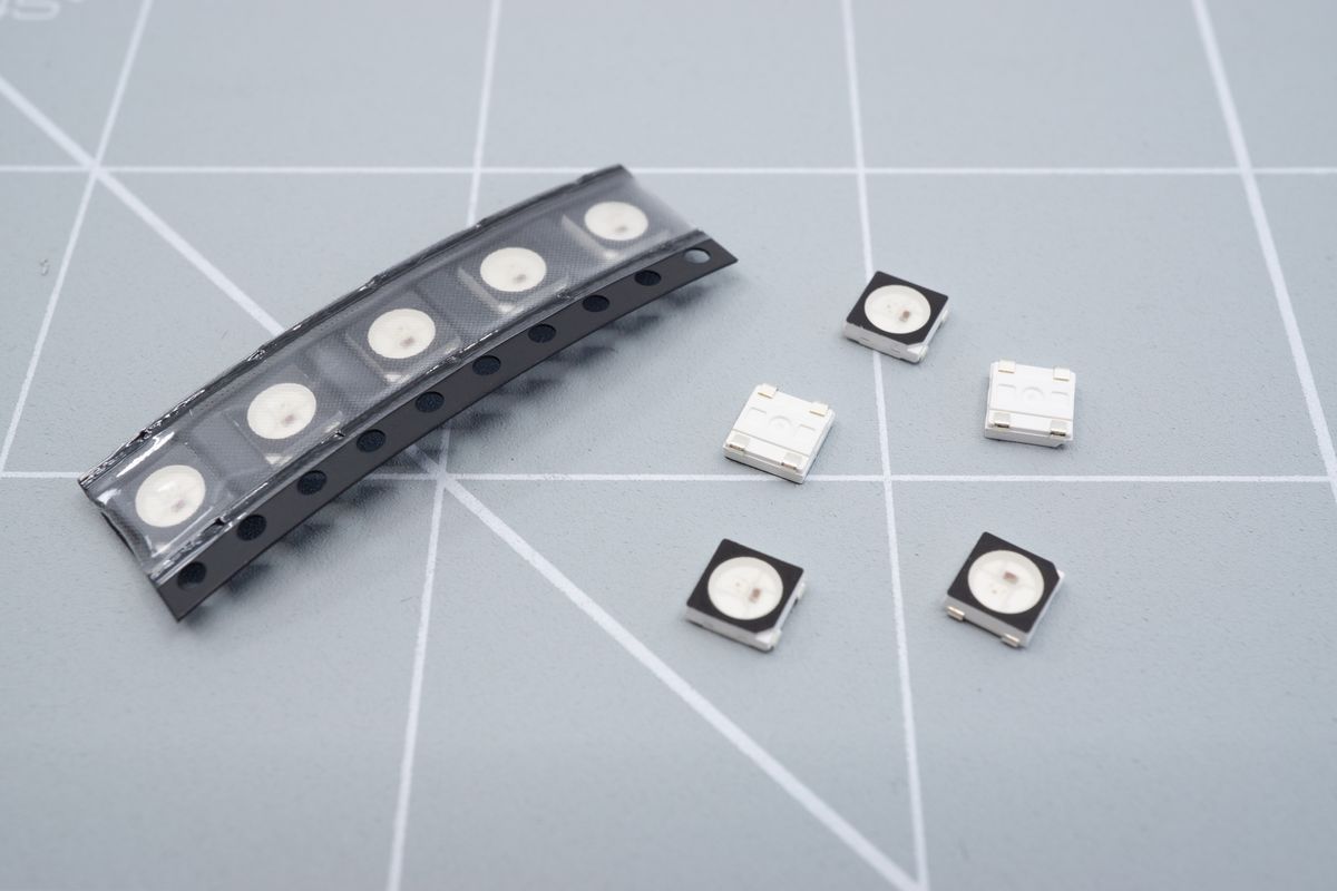
These LEDs are also SMD components.
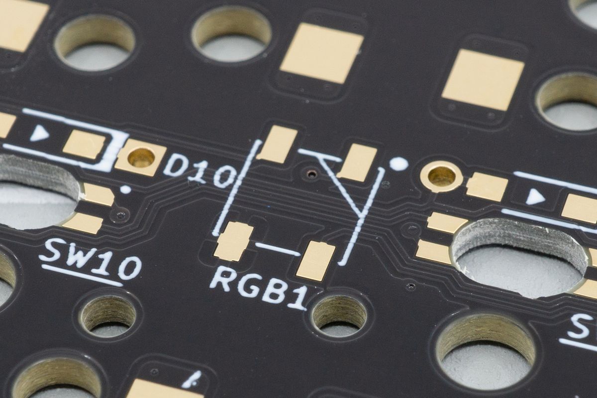
They get soldered to these footprints, labelled with "RGB". Our kits have larger pads than usual, making them easier to solder for beginners.
RGB LEDs provide colourful light. These underglow LEDs are a little bigger than the backlight ones, but don’t have legs. They glow toward the bottom of your keyboard, which can make for a cool effect with an acrylic bottom plate.
Reset Buttons
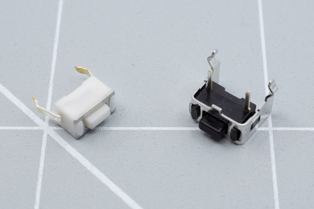
Most kits will use a button similar to the one on the right. If your kit needs the smaller button on the left, it'll be contained in the larger bag that also had the PCBs in it.
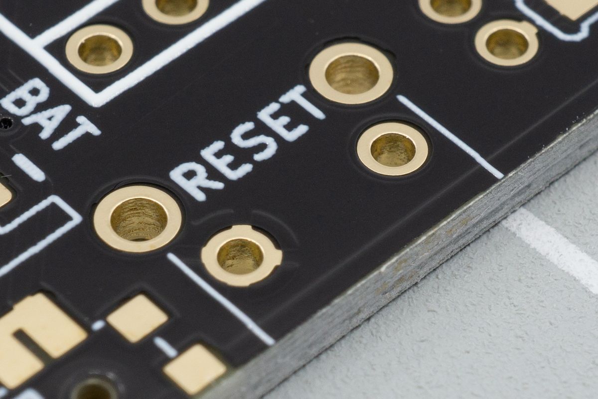
And on most kits, the button will be soldered to a footprint like this, aptly labelled RESET.
Reset buttons are small, tactile buttons that provide the function to reset your keyboard. Its working differs slightly depending on the controller you use, but in general you can press this for a second or two for your controller to enter “bootloader mode”, in which you can flash new firmware to your keyboard.
TRRS Jacks
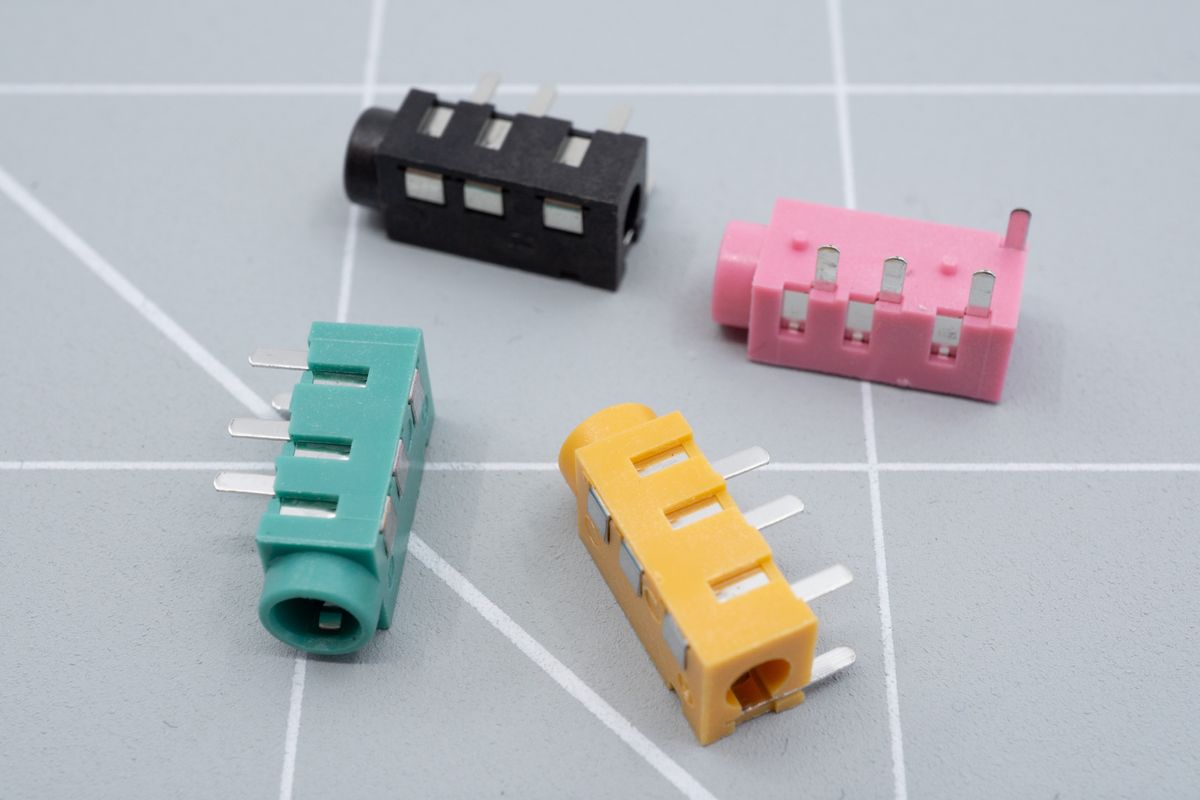
We carry these TRRS jacks in a few colours, but black is the most popular and is included in all kits.
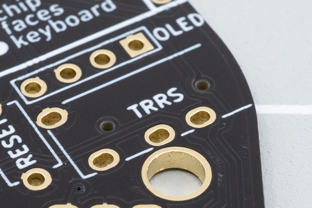
The TRRS jacks get soldered to their own footprint, too.
You might be familiar with these already: they’re 3.5mm jacks that are also used for wired headphones, among many things. For our keyboards, they’re used to connect both halves together using a TRRS cable.
They are optional when using a wireless controller, but you can install them anyways.
TRRS or TRS Cable
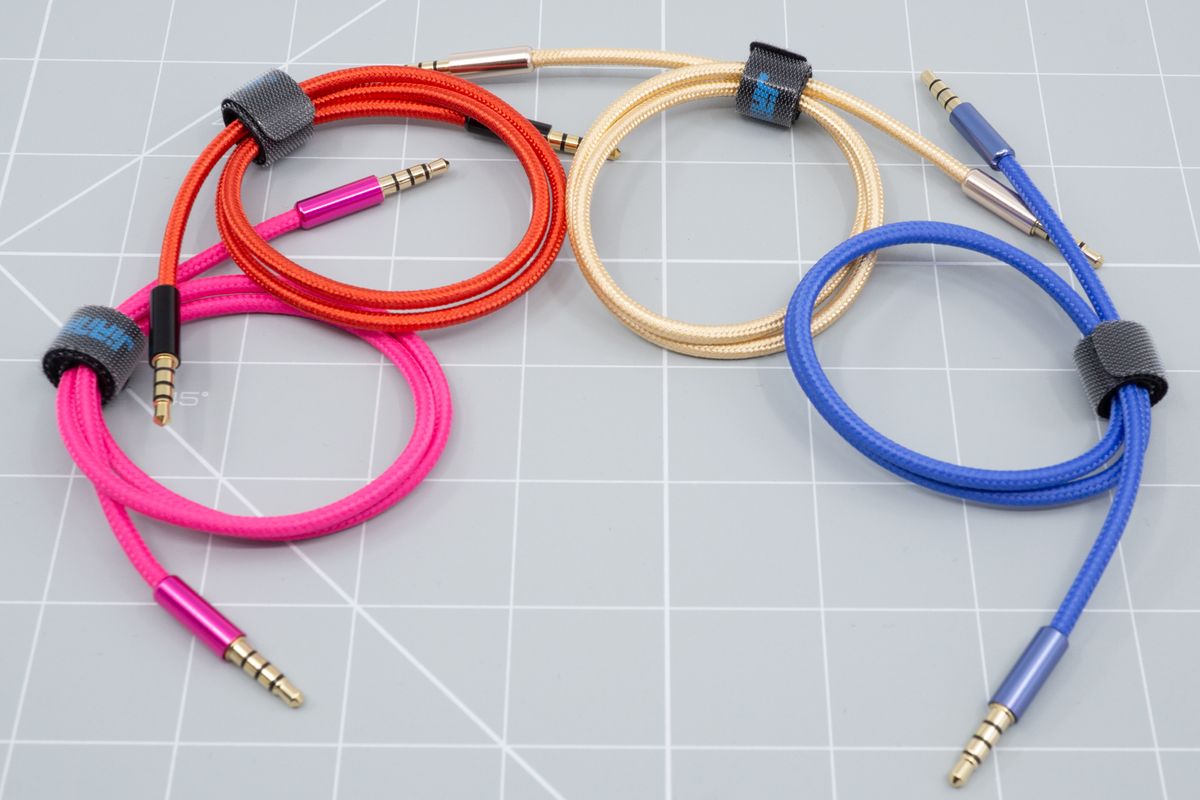
Braided TRRS cables in a few colours.
A TRRS cable is a cable with a 3.5mm plug at both ends. You can identify it by the four sections it has on each end: a Tip, two Rings, and a Sleeve. It is used to connect two halves of a keyboard together. Because of the way it is constructed, it’s best to only unplug this cable after you’ve disconnected the USB cable from your keyboard. You risk damaging the controller otherwise, as removing the TRRS cable will short its contacts.
Aurora kits are also compatible with TRS cables, but not with TRS-to-TRRS ones.
For more information, see What is a TRRS cable and why would I need one?
Switch Sockets
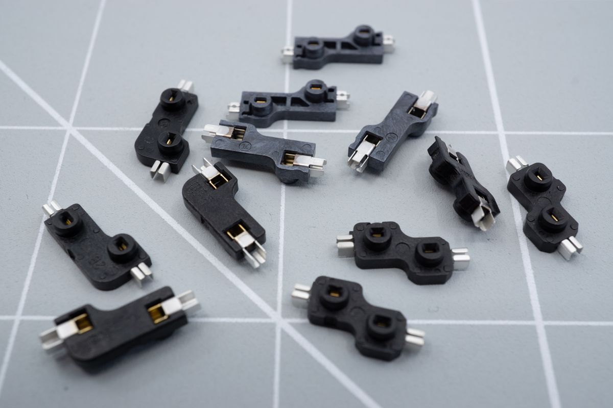
A few hotswap sockets. Those compatible with MX-switches will usually have an L-shape, while the ones for Kailh Choc low profile switches will be kind of S-shaped.
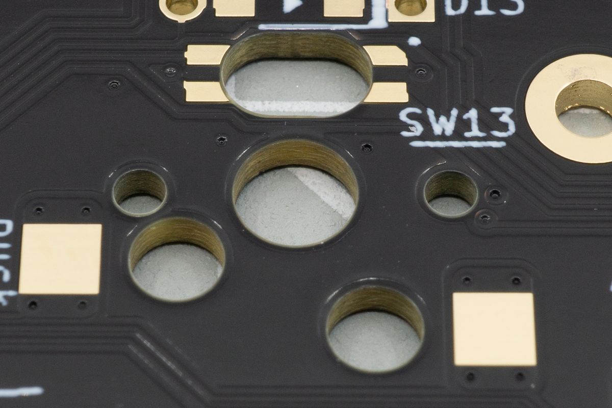
The sockets drop with their tall parts into the two holes, and the metal ends get soldered to the square pads.
Switch sockets are used to be able to “hot swap” the switches on your keyboard. This means that you won’t have to solder your switches directly, and can thus easily remove and replace them if you’d like to try other flavors or if one happens to break.
The MX Hotswap and Choc Hotswap variants of the kit will come with their required sockets included, the Handsolder variant can optionally use Mill-Max sockets which are sold separately.
Microcontroller
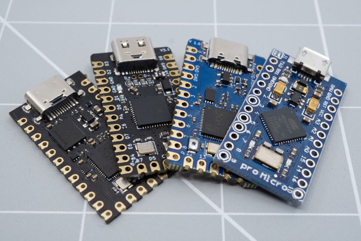
A bunch of compatible microcontrollers. We usually recommend our Liatris, as it's tailor-made for split keyboards.
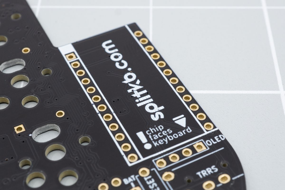
The controller gets soldered to these two rows of pins. Usually you'll hot swap them, meaning you don't solder the controller directly to the PCB.
The microcontrollers are the brains of your keyboard. For our kits, you’ll need controllers that are Pro Micro-compatible. While many are compatible, these days we find that for wired keyboards you want a controller with an RP2040 controller, which includes the powerful Liatris and the less-common Elite-Pi.
For wireless controllers, there's less to choose from: we recommend the nice!nano.
Older controllers are available, too, based on AVR microcontrollers such as the Elite-C and the more budget-friendly Pro Micro. Due to the increasing capabilities of QMK and the fancy things people do with firmware, you'll quickly find them to lack the required space, though.
Microcontroller Sockets and Pins
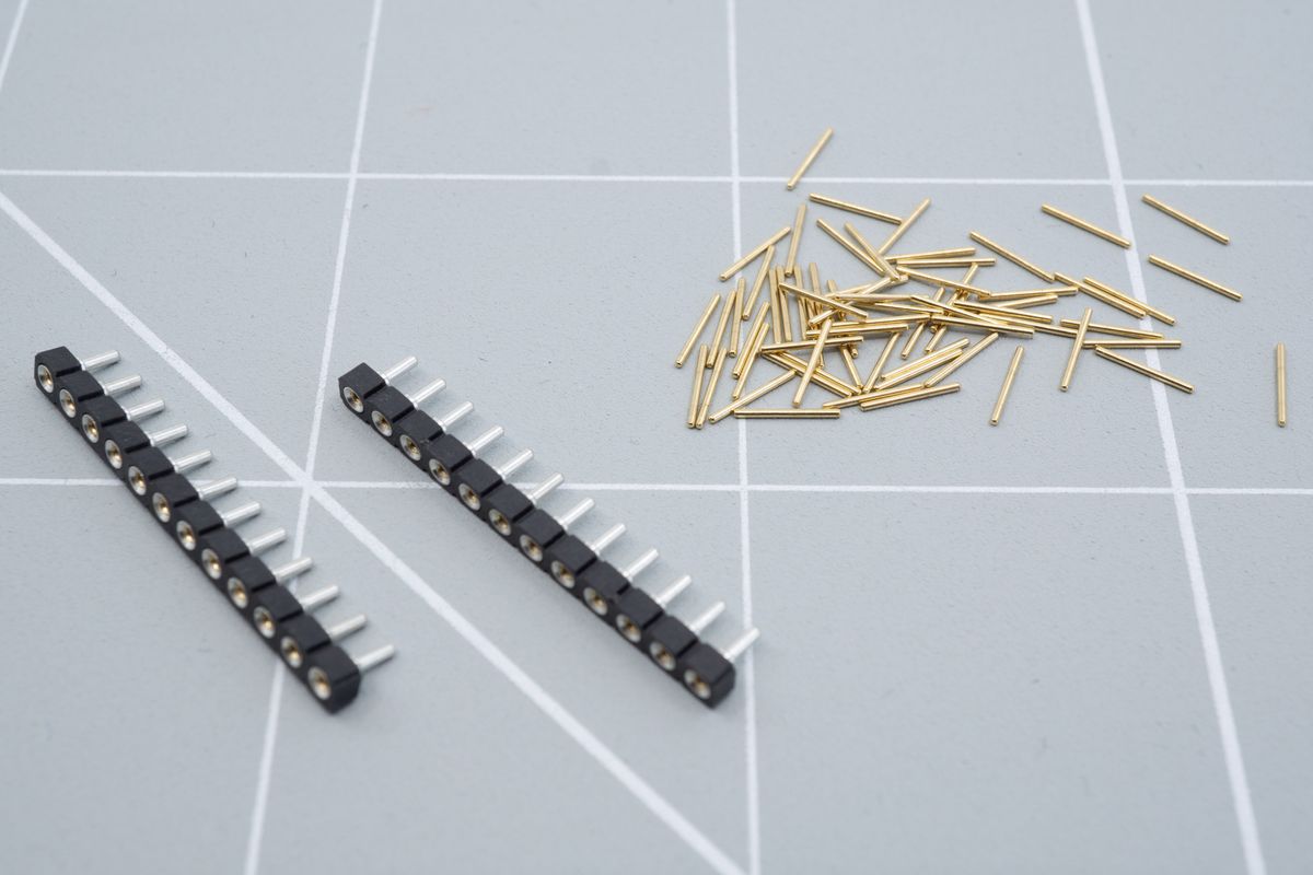
Socket strips and mill-max pins. You can also get fancy header pins, which basically put all the pins on a single strip for easy assembly.
Desoldering a microcontroller is a tall order, especially for people new to soldering, and is still quite cumbersome for seasoned builders. Controllers can also be costly, and sockets can help avoid damage while desoldering and promote reuse when you’d like to use your current controller on a new keyboard. If you’re confident in your skills, sockets aren’t a necessity, but we definitely recommend using them.
This goes doubly so for the Pro Micro, whose USB connector is known to break off quite easily. Our other controllers use a more durable USB-C connector and are less susceptible to this issue, but doing a Pro Micro build without sockets is probably a bad idea.
Instead of the pins we sell alongside the sockets you can also use the leftover legs from diodes as well. They’re a bit more finicky to work with than the pins and less durable, but if your kit uses through-hole diodes they’re also free.
Microcontroller socketing is explained in more details in Why would I want to socket my microcontroller?
Switches
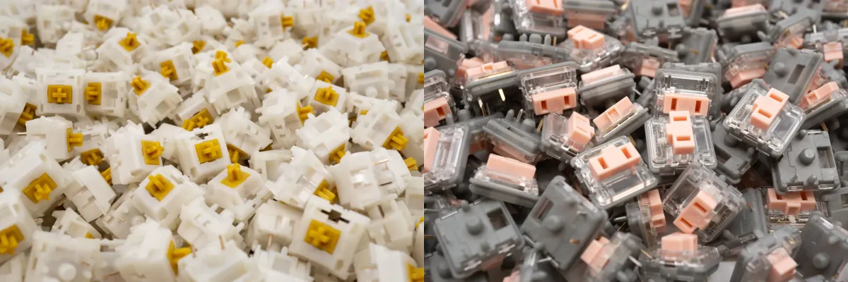
MX switches on the left, Kailh Choc low profile switches on the right.
Switches are the parts that make the actual keypresses work, in conjunction with the diodes and controllers. They are available in many kinds: the common “MX” style switch which encompasses a great number of brands and characteristics, and low profile Choc switches which are also available in many flavors.
Of course, the MX-style switches are compatible with MX-style kits, Chocs are compatible with Choc-style kits, and the handsolderable kits are compatible with both.
The product page for your kit will tell you how many switches you’ll need.
Choc v2 switches are not compatible with either kit and aren’t sold at splitkb.com.
Keycaps
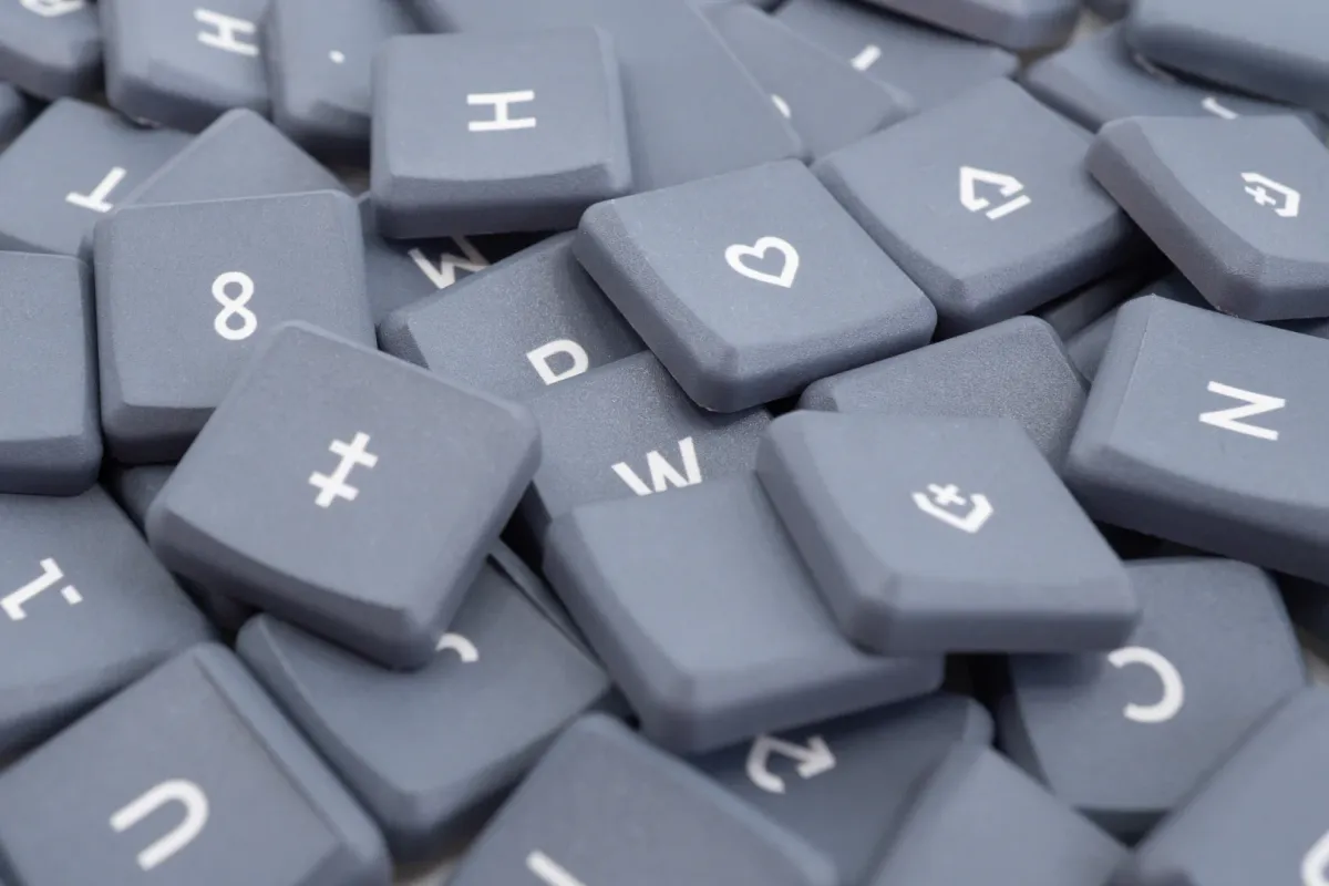
White on Grey MBK choc keycaps.
Keycaps are the (usually) plastic bits that go on top of your switches. Sure, you could type without them, but it’s not very comfortable!
You’ll need MX-style keycaps for MX-style switches, identifiable by the plus-shaped opening on the bottom of the keycap. For Choc-style switches, you’ll want to look for two bar-shaped stems, like I I.
The product page for your kit will tell you how many keycaps you’ll need, and in which sizes.
Case
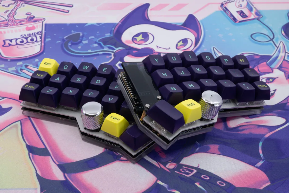
An Aurora Corne with some bold colours.
A case consists of several parts, usually at least a top plate, bottom plate, and hardware to mount it: screws and spacers. Usually, a transparent cover is also purchasable for the OLED display. For some cases, an opaque cover is also available when you want to hide the OLED area.
Although some hardcore enthusiasts choose to use their keyboard caseless, you will probably want to include at least a plate case in your build. Please do not try to use hotswap switches without a case - the switches will not remain in place.
Bumpons
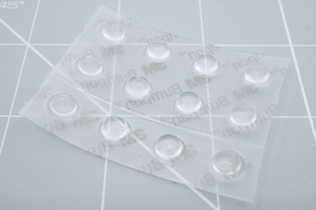
A strip with twelve transparant rubber bumpons.
Bumpons are adhesive rubber domes which you can mount on the bottom of your case (or directly to the PCB when not using a case). They provide friction so your keyboard won’t slide around, and they protect both the case and the work surface from scratches.
Bumpons are also available separately if you want to create your own case or go caseless.
Rotary Encoders and Knobs
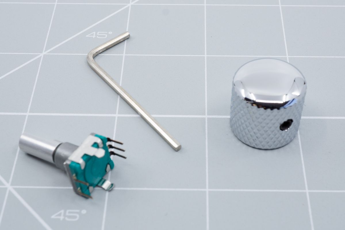
A rotary encoder, allen key and shiny metal knob.
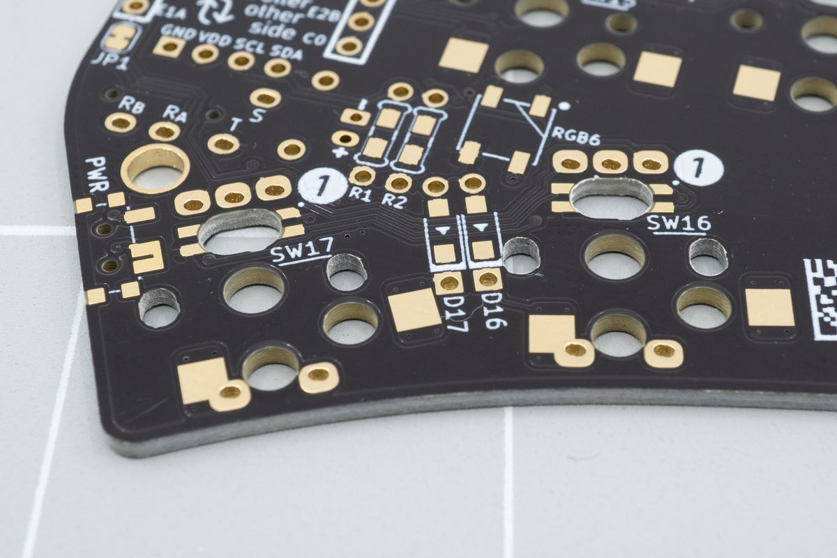
Rotary encoders can usually be installed optionally instead of a normal switch.
Rotary encoders make the knob go round - they make it easy to control things like volume, display brightness, but also make it possible to skip through windows. You can map any key to the twist (and press!) of an encoder, and so doing more advanced things like scrubbing through history is possible too, simply by mapping CTRL+Z and CTRL+Y (or equivalent) to your encoder’s layout.
For more ideas on how to use encoders, see How can I use a rotary encoder?.
OLED Display
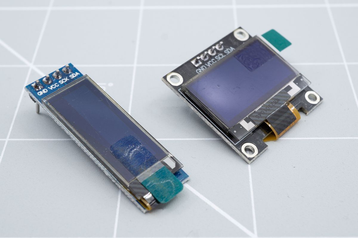
A tall 128x32 pixel OLED display, and a wider 128x64 pixel OLED display.
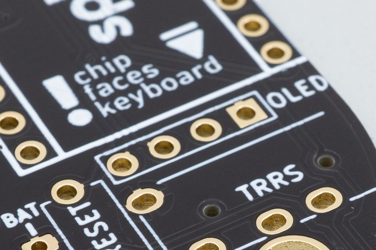
These displays are usually installed on top of the controller, using this 4-pin footprint.
An OLED display can display status information such as the currently active layer, words typed per minute, and can also display graphics like a custom logo or background. There are many other uses for OLED displays, and they come in various sizes, like the common 128x64 pixels, or the taller 32x128 pixel display.
Each kit will have a preferred OLED size it works with, though you might be able to swap out a smaller display for a larger one if it fits. The kit’s product page will list its preferred display size.
OLED Sockets
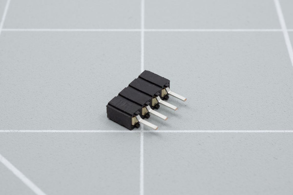
Remove your display without having to desolder using a 4-pin socket.
If you need to remove your OLED display, for example when you need to rework your controller or would like to remove it, sockets will make desoldering the OLED unnecessary. Desoldering the OLED can be relatively easy, but it’s a nice comfort option to have.
JST Jacks (Wireless only)
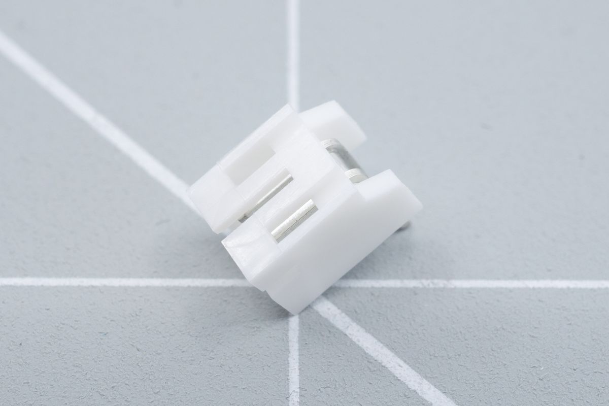
A 2-pin JST jack.
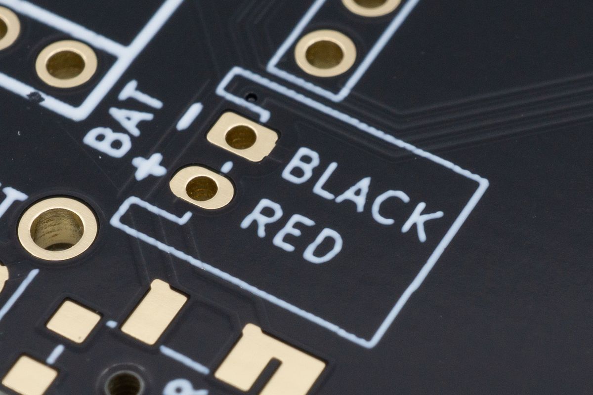
If the kit supports it, it'll have a footprint like this with an outline for the jack. If not, it'll just have two pads without an outline instead.
Only useful when using a wireless controller like the nice!nano, a JST jack is supported on most Aurora and other splitkb.com kits. They allow you to click in your battery instead of soldering it directly to the board. Pay attention to the polarity though - make sure the plus lines up with the plus, and the minus with the minus, because batteries can get spicy otherwise!
Power Switches (Wireless only)
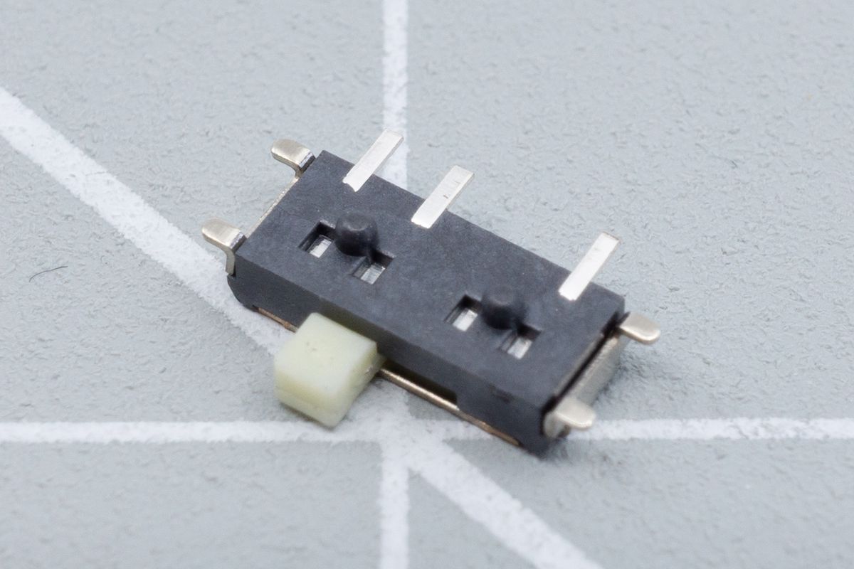
The power switch, laying on its back.
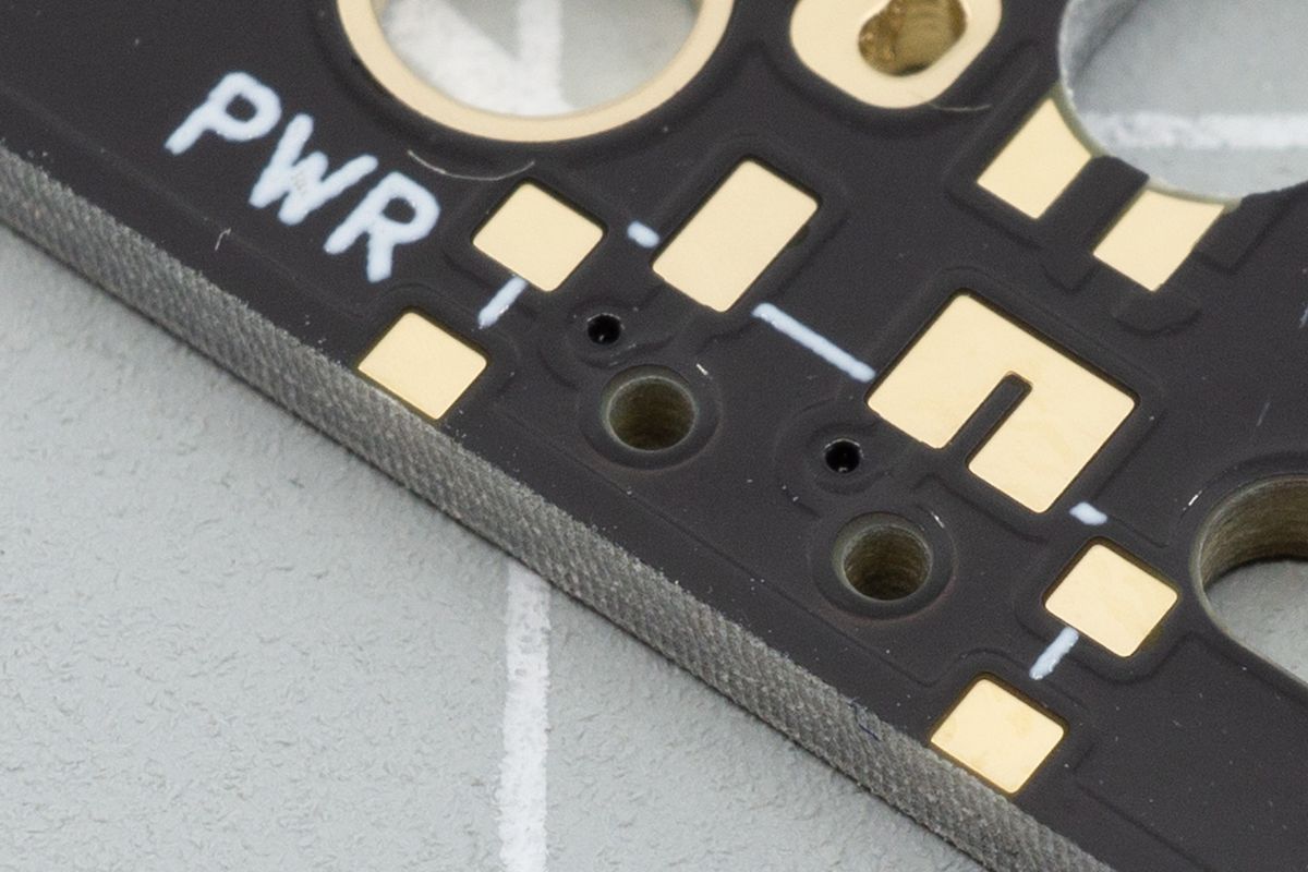
The footprint where the switch will be installed, labelled "PWR".
Only useful when using a wireless controller like the nice!nano, a power switch allows you to cut the power between the battery and the controller. While the controllers power saving mode is pretty efficient, you might want to prevent accidental keypresses while carrying the board, and so every kit supports a power button.
Batteries (Wireless only)
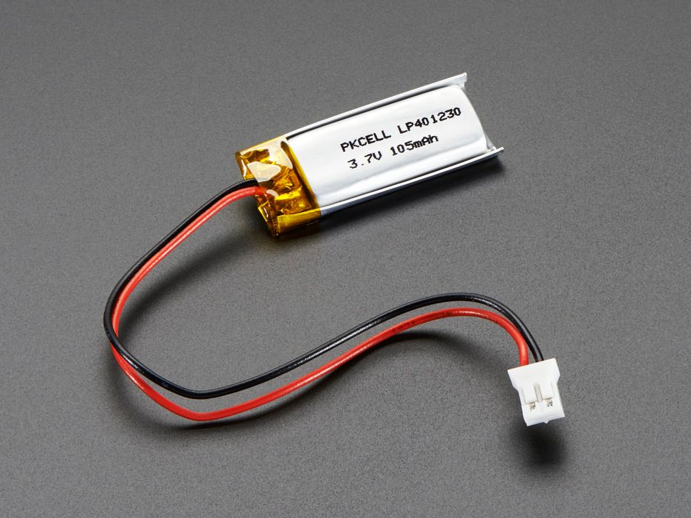
A small battery, which will fit below the controller. Image copyright by Adafruit.
Only useful when using a wireless controller like the nice!nano, a battery powers the actual board. While it is possible to power your board using a USB cable, that’s not exactly why you got the wireless controller ;)
Unfortunately, due to (understandably) very strict restrictions on shipping batteries internationally, splitkb.com currently does not sell batteries, so you will have to acquire them somewhere else.
We can recommend the following stores, or their resellers:
Introduction
How to read the Aurora build guide and what to expect.
Known issues
Check on the issues in our kits that we know about.

