OLED displays
You should perform this step if you are using OLED displays. If not, you can go to the next step using the button below.
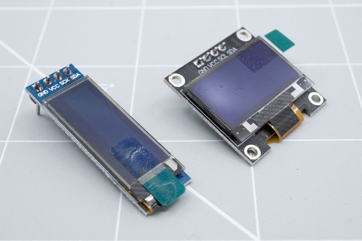
Two OLED displays, with a 128x32 pixel display on the left and a 128x64 pixel display on the right.
Soldering your display
If you’re using OLED sockets, please skip to the sockets section on this page.
The components on the bottoms of OLED displays are conductive, and can touch with the pins on your keyboard’s controller. To prevent shorts from happening, causing weird behavior and possibly damage, cover the bottom of your OLED display with non-conductive tape. We used electrical isolation tape, but Kapton tape will work as well.
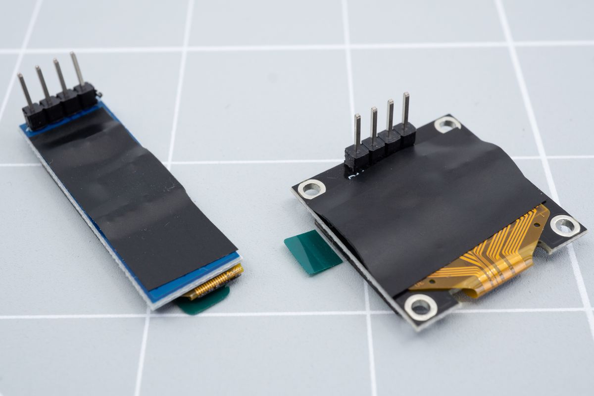
The back side of the displays, covered in isolating tape.
Insert the OLED display from the top of the PCB. You can use a piece of tape to hold it in place while you work.
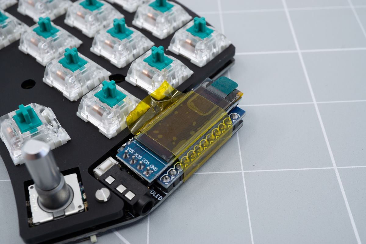
A piece of tape keeps the display in place while soldering.
Flip the board around, then solder a single pin of the display.
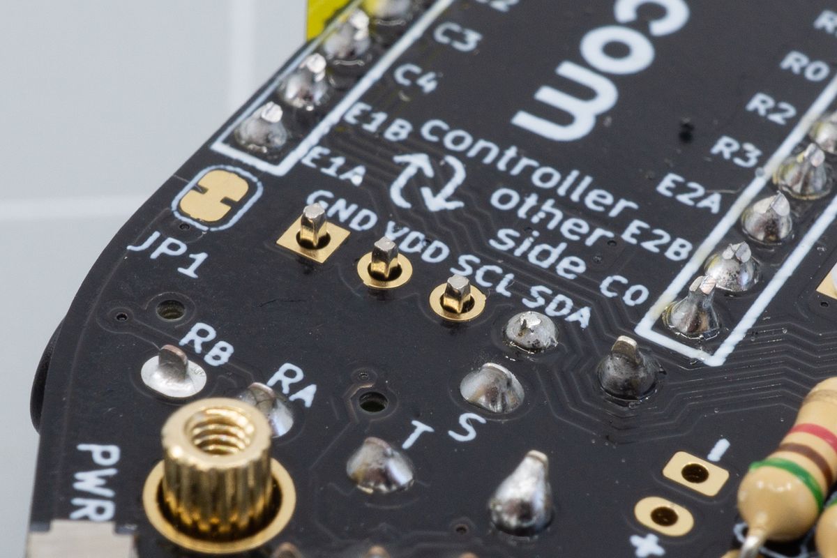
The back side of the keyboard, with a single display pin soldered.
Flip the board around again and check whether the OLED is aligned properly, both horizontally and vertically. Look at your keyboard from the top as well from the side to verify the alignment.
If it’s not aligned properly, heat up the single solder joint and move the display around until you’re happy with how it looks.
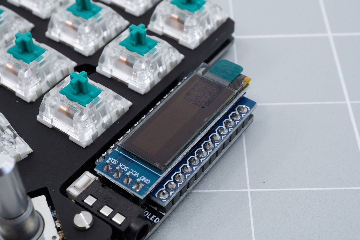
The aligned display. You can remove the tape after soldering the first pin to make it easier to gauge the alignment.
Solder the remaining three pins.
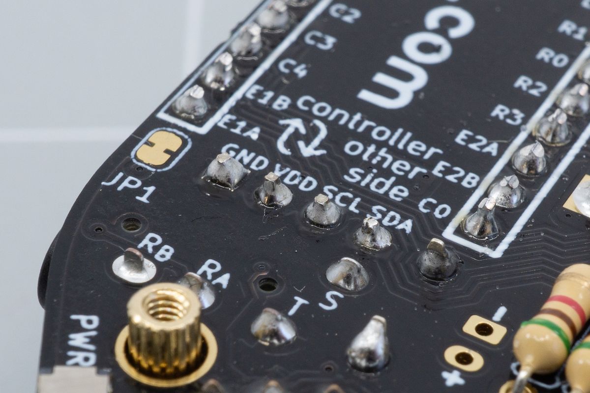
All display pins soldered.
OLED sockets
The components on the bottoms of OLED displays are conductive, and can touch with the pins on your keyboard’s controller. To prevent shorts from happening, causing weird behavior and possibly damage, cover the bottom of your OLED display with non-conductive tape. We used electrical isolation tape, but Kapton tape will work as well.

The back side of the displays, covered in isolating tape.
When using sockets, you could just insert your OLED into them. However, that may be too tall to fit underneath the OLED cover of the case. For that reason, trim about 1.5mm off of the OLED’s legs using flush cutters.
Start by trimming off a tiny bit from one leg first, then insert the display into the socket to see how far you've got remaining. You can keep whittling pieces off until you're happy. That first leg can then serve as a guide to cut the remaining legs to the right length.
The sockets are about 4mm deep, which will be the minimum length that'll need to remain on the display.
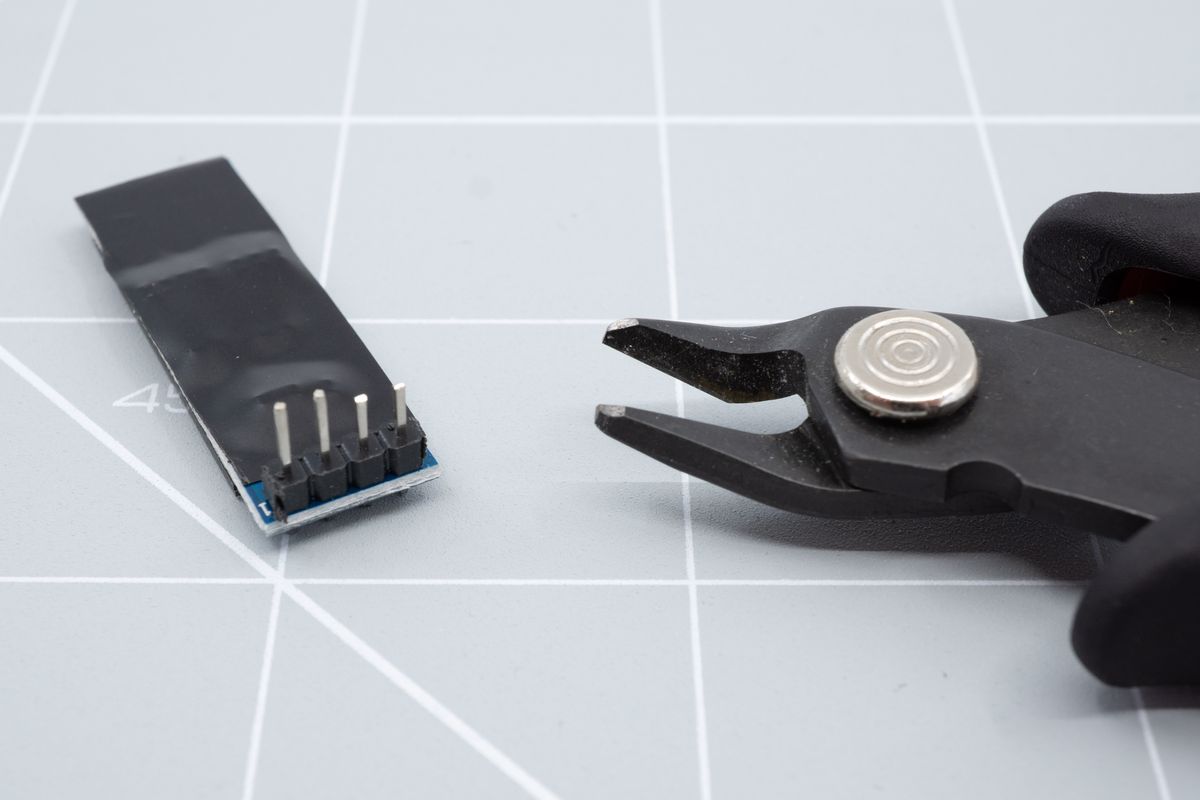
Trimming the first two legs.
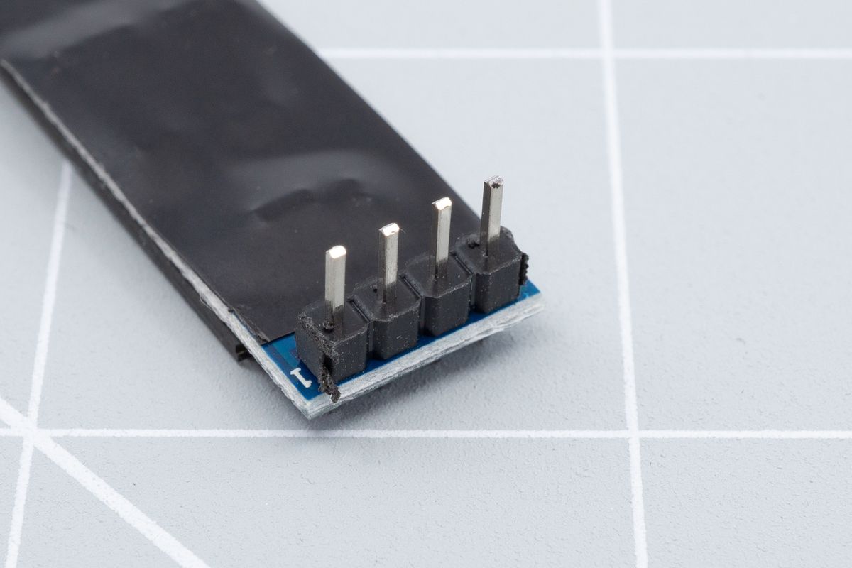
All legs trimmed, approximately to the same size.
After trimming the legs, insert the OLEDs into the sockets. All done!
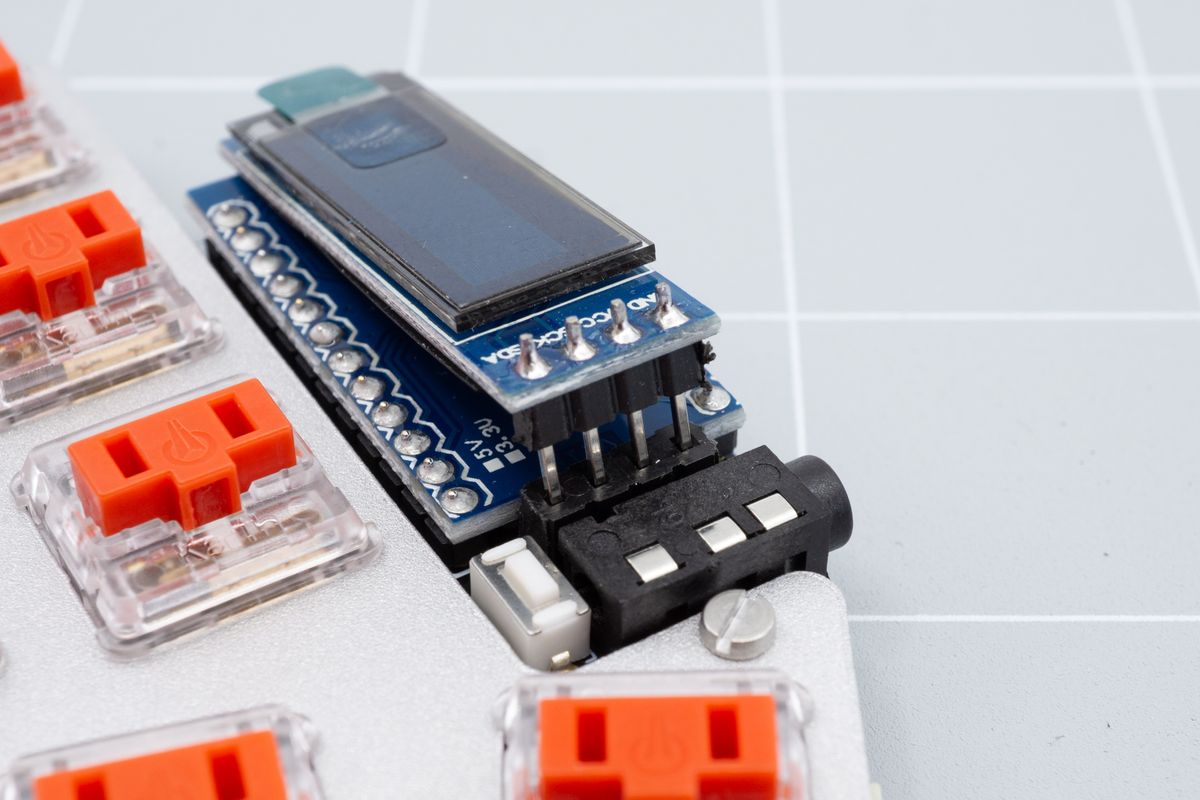
Aligning the display with its socket.
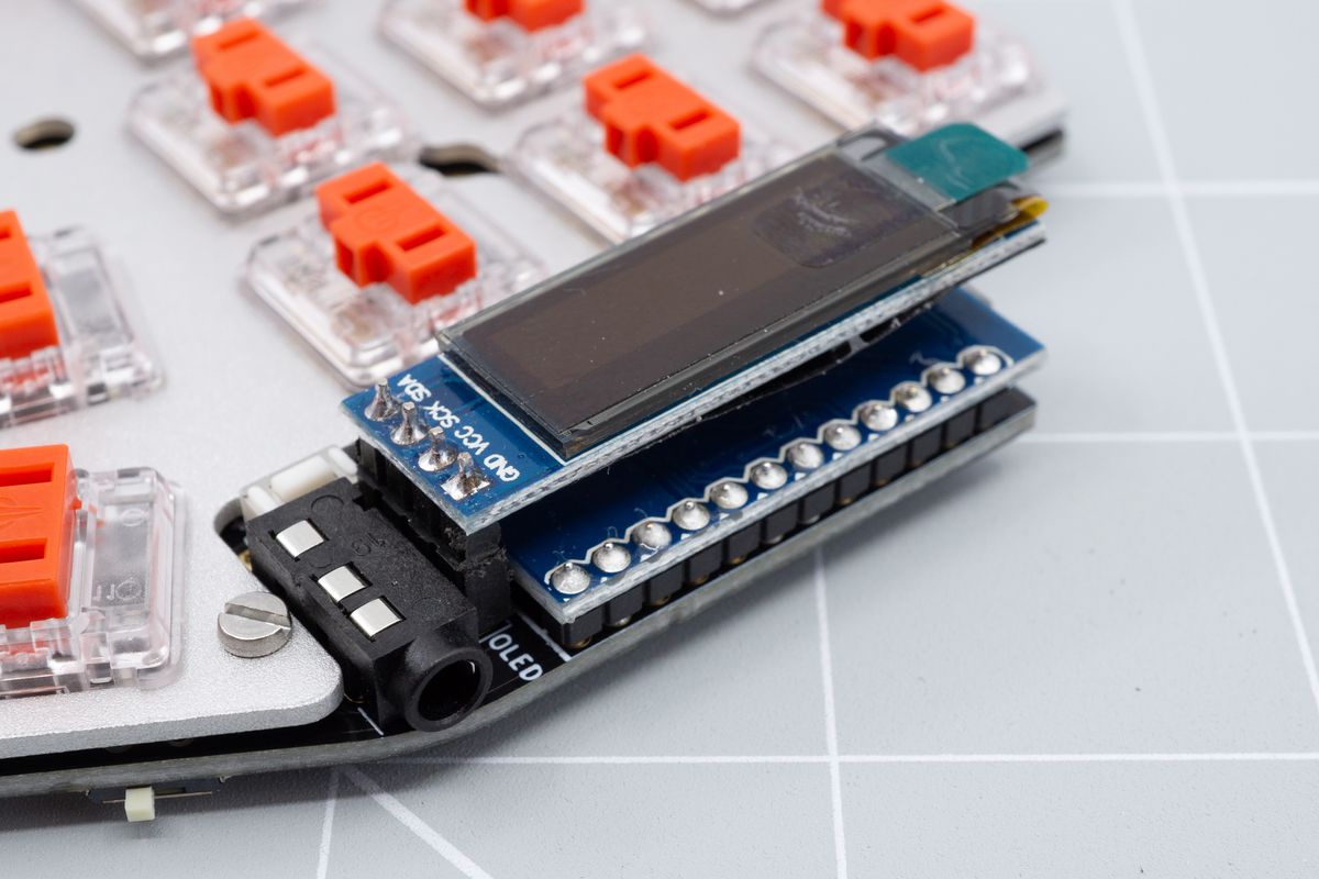
The display inserted into the socket. Notice how the plastic piece sits flush with the socket.
The display has a protective foil layer on it, with a pull tab. You can pull on that pull tab from the top of the display to remove it after you’re done assembling the keyboard (and before putting on your case’s OLED cover window).
If you'd like for the display to sit lower still, you can remove the plastic piece from the legs by tugging on it with pliers, it can slide off the legs with a little effort.
Switches
The parts that make a mechanical keyboard mechanical.
Case assembly
A case protects the components of your keyboard.

