Rotary encoders
You should perform this step if you are going to use one or more rotary encoders. If not, you can go to the next step using the button below.

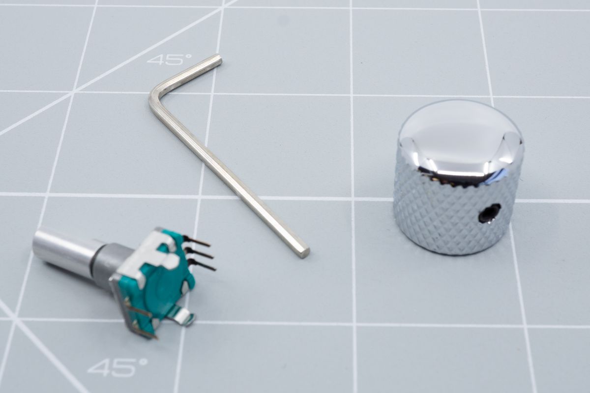
A rotary encoder, allen key and an encoder knob.
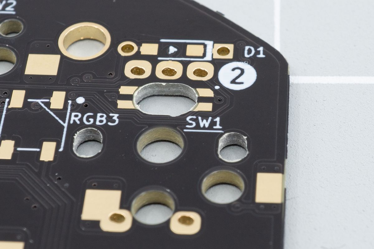
If you look at the bottom of the PCBs, you’ll see a few spots marked with white circles with a number in it. On many kits, you’ll see one or more spots marked with (1). Some kits may also have a (2) or even a (3).

An encoder footprint, overlapped with a switch footprint.
These marked spots are spots where you can choose to install an encoder. Spots that share the same number, also share the encoder’s data pins, so it’s recommended to only install a single encoder per number - encoders sharing the same number might not work, or might do the same thing, which isn’t very helpful.
If your keyboard kit only has (1)s, that means your keyboard supports up to one encoder per half. If it also has (2)s, that means it supports up to two encoders per half, et cetera. If you’d like to install your encoder on a (2) position, you won’t need to also install one on a (1) position: you’re free to use as many or as few encoders as the keyboard supports.
To install an encoder, first insert the side with the three little legs partly into their pads on the PCB. Then turn the encoder toward the remaining two pads and insert them partly as well. Lastly, press the encoder down, pressing the side legs into their corresponding holes. This may require a bit of force, though you shouldn’t have to overdo it.

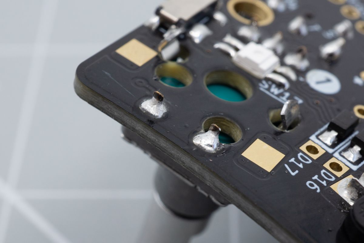
A soldered encoder, looking at the bottom side of the keyboard. Some pads may overlap with switch holes, but you'll still be able to form a good joint.

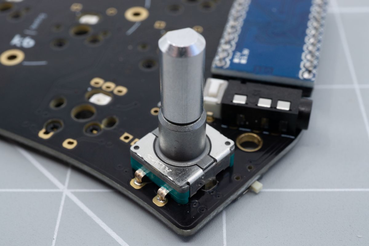
A soldered encoder, looking at the top side of the keyboard.
If your keyboard supports a single one encoder per half, then there's nothing to remember: there'll only be configuration for a single encoder.
Batteries
Batteries are used to power a wireless controller.
Switches
The parts that make a mechanical keyboard mechanical.

