Per-key RGB
You should perform this step if you chose the SK6812MINI-E per-key RGB LEDs. If not, you can go to the next step using the button below.
Per-key RGB LEDs are placed near every switch, marked by SW followed by a number, like SW12. They are optional, you only need to do this step if you’ve purchased per-key RGB LEDs with your kit.
The LEDs can be oriented in two ways. It is absolutely crucial that you get the orientation right. Familiarize yourself with the orientation markers on both the LED and the PCB: The LED will have a single angled corner, the PCB will have a dot marking one pin.
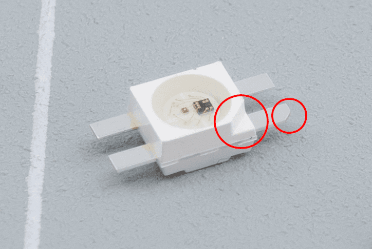
The LEDs have a little angle in both the housing as well as one of the legs, indicating their orientation.
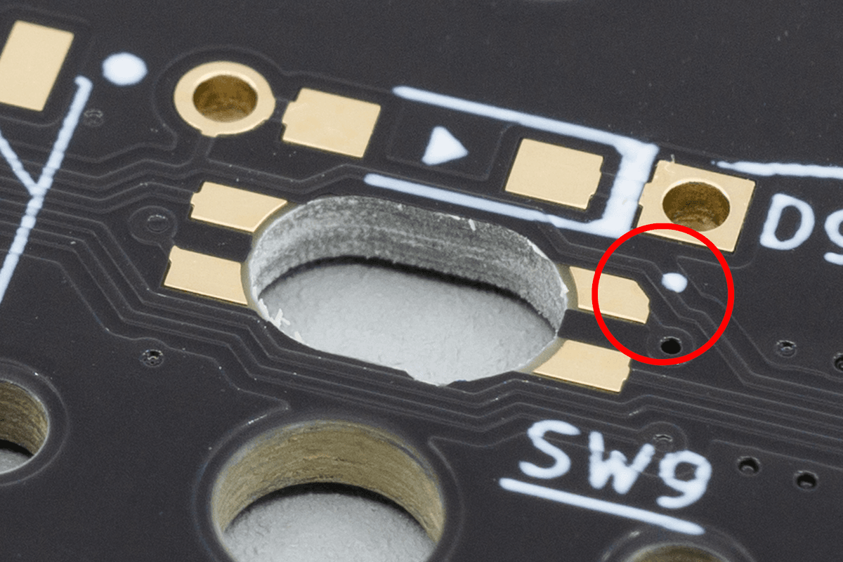
The footprint on the PCB has the same little angle in it, which should match with the angle of the LED.
Once you have figured out the orientation, solder a little bit of tin to the first pad. This will make soldering the other pins easier.
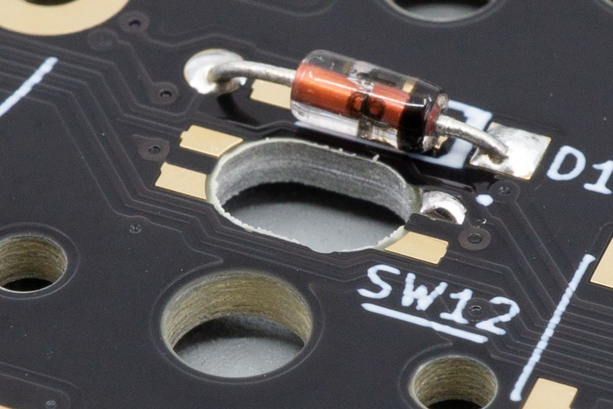
One pre-tinned pad. You don't need a lot of solder, as the pad is pretty small.
Place the LED on top of the pads. Make sure the orientation is correct.

Left: A diode that's oriented incorrectly. Right: a correctly oriented diode. Match the shapes and you'll be fine.
Solder the first pin, making sure that the other pins are aligned properly. While heating the pin with your soldering iron, use a pair of tweezers to align it.
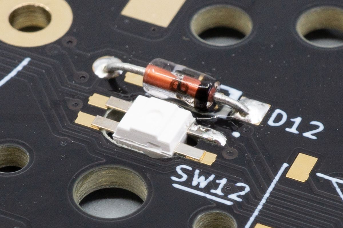
The first leg of the LED is now soldered.
Now solder the rest of the pins.
Remember, heat sensitive. Solder only one pad per LED and move onto the next LED to allow them to cool down from soldering, and come back for the next pad once you have done all other LEDs.
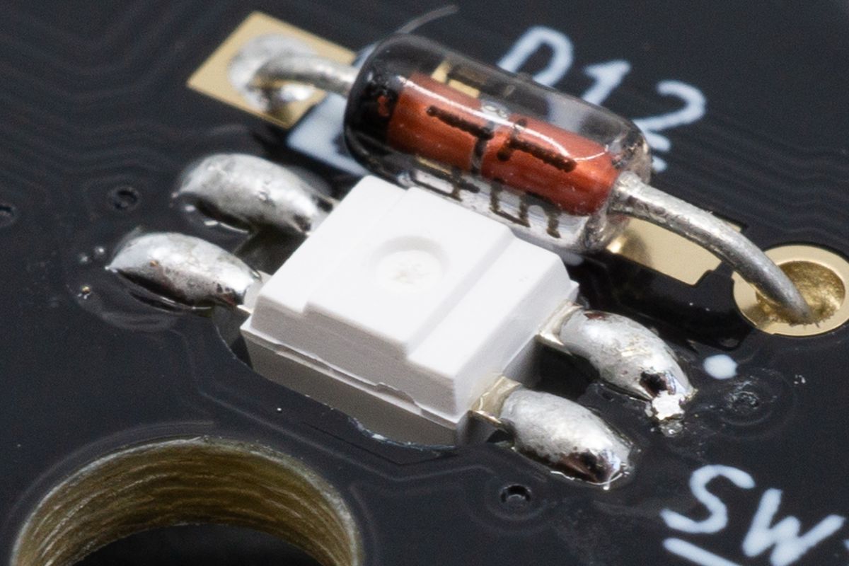
All of the legs of one LED soldered.
Flip the board over and double-check that you soldered all LEDs in the right orientation.
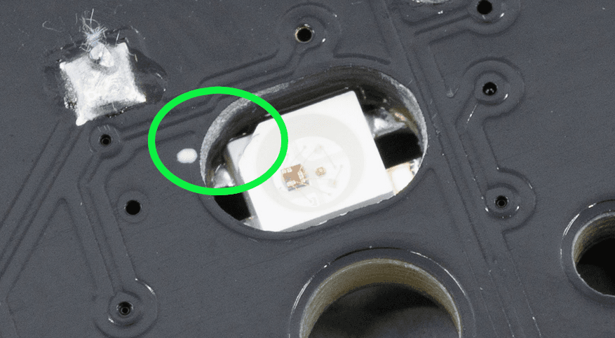
The solder hides the little angle on the leg, so the only way to deduce the orientation afterward is by looking at the top of the LED.
If they are all oriented correctly, you are done with the per-key RGB backlight.
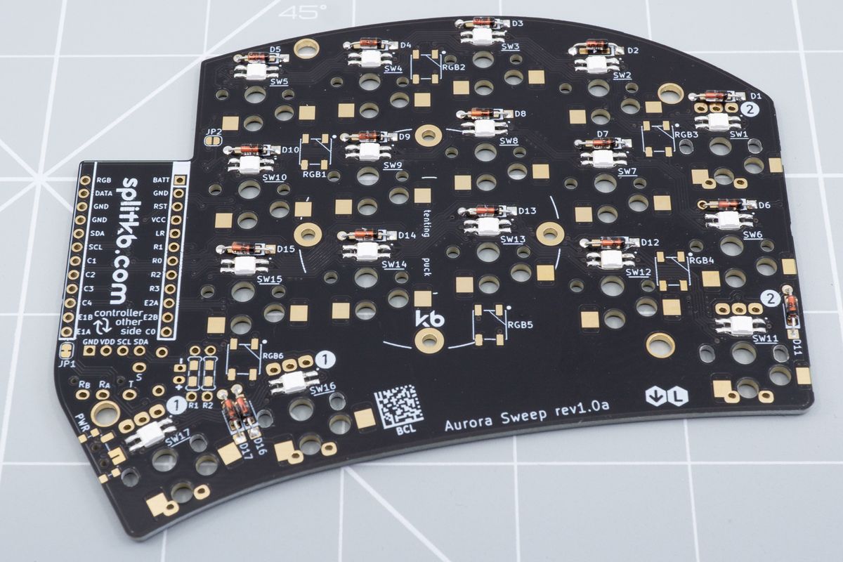
The bottom side of an Aurora Sweep with all of its per-key RGB LEDs soldered.
Not using per-key RGB, and only using underglow LEDs instead? Then you can just ignore this jumper. You won't need to adjust anything to do that. Easy!
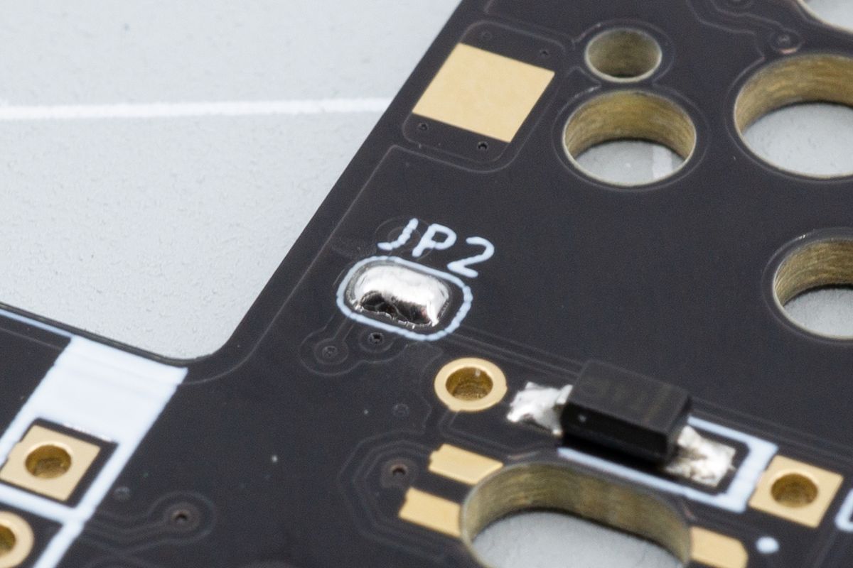
A soldered JP2 jumper bypasses the underglow LEDs.
Diodes
Diodes ensures your keyboard's keypresses get registered reliably. Learn how to install them here.
RGB underglow
Light shining down on your desk from the bottom of your keyboard. Learn how to solder RGB underglow LEDs.

