Switch sockets
You should perform this step if your kit includes hot-swap sockets, which are the MX and Choc kits (and excludes the "Hand" version). If not, you can go to the next step using the button below.
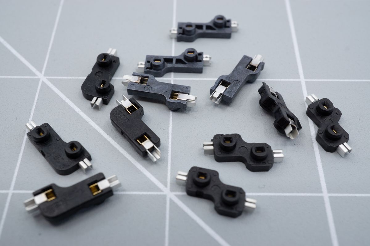
A few kinds of switch sockets: Starting at the top, moving clockwise: Outemu MX sockets, Kailh Choc sockets, Kailh MX sockets.
Each socket has a top and a bottom side, it’s easy to tell: the bottom side is completely flat, while the top side will have two small cylinders extending from them.
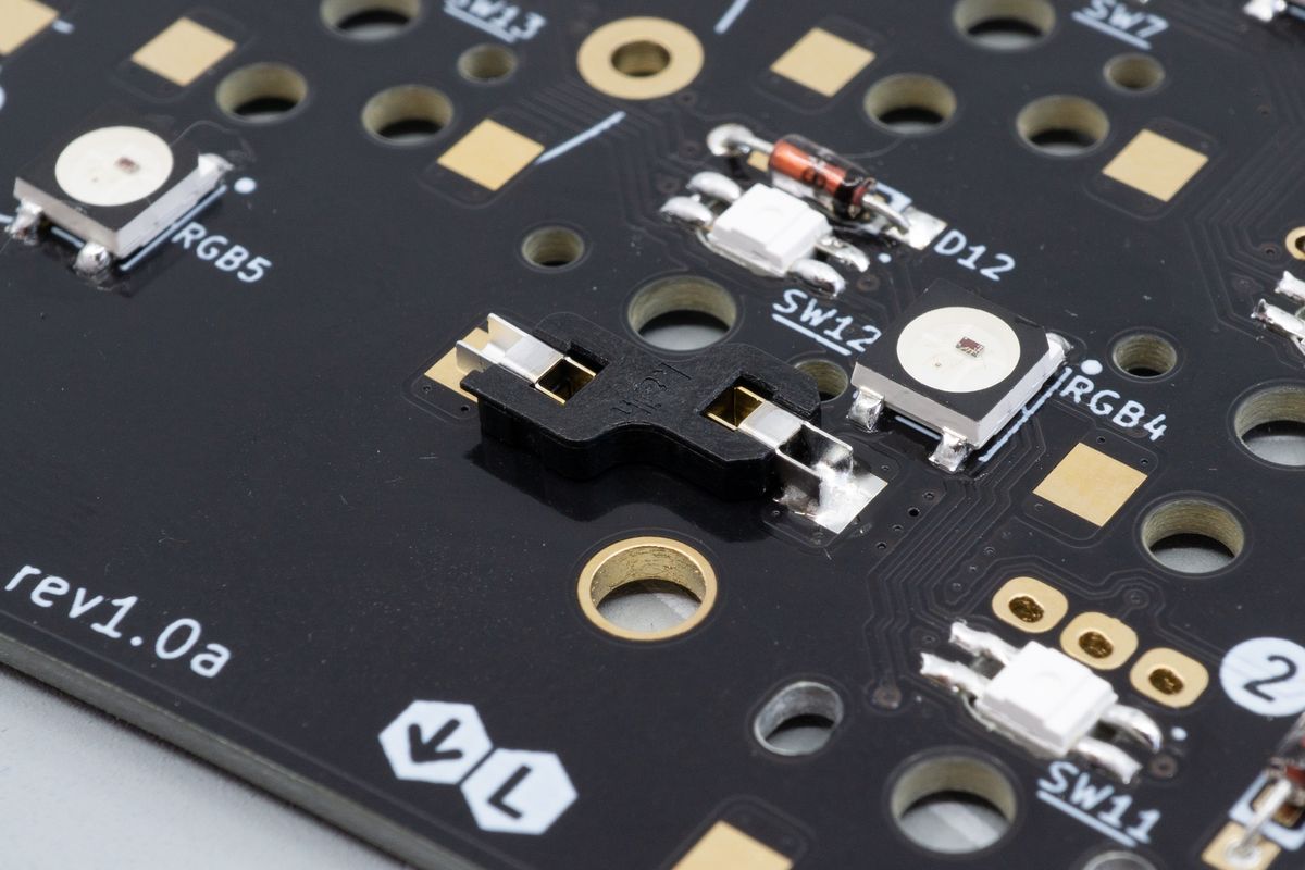
Orient the PCB with its bottom (flat) side facing toward you, and place a hotswap socket into the PCB on a switch position (marked SW followed by a number, like SW12). The bottom of the hotswap socket will be facing you.
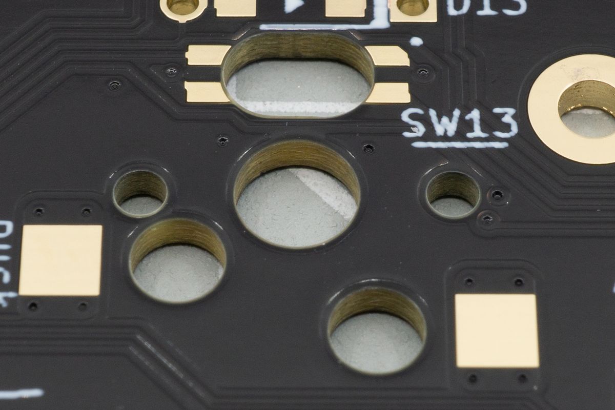
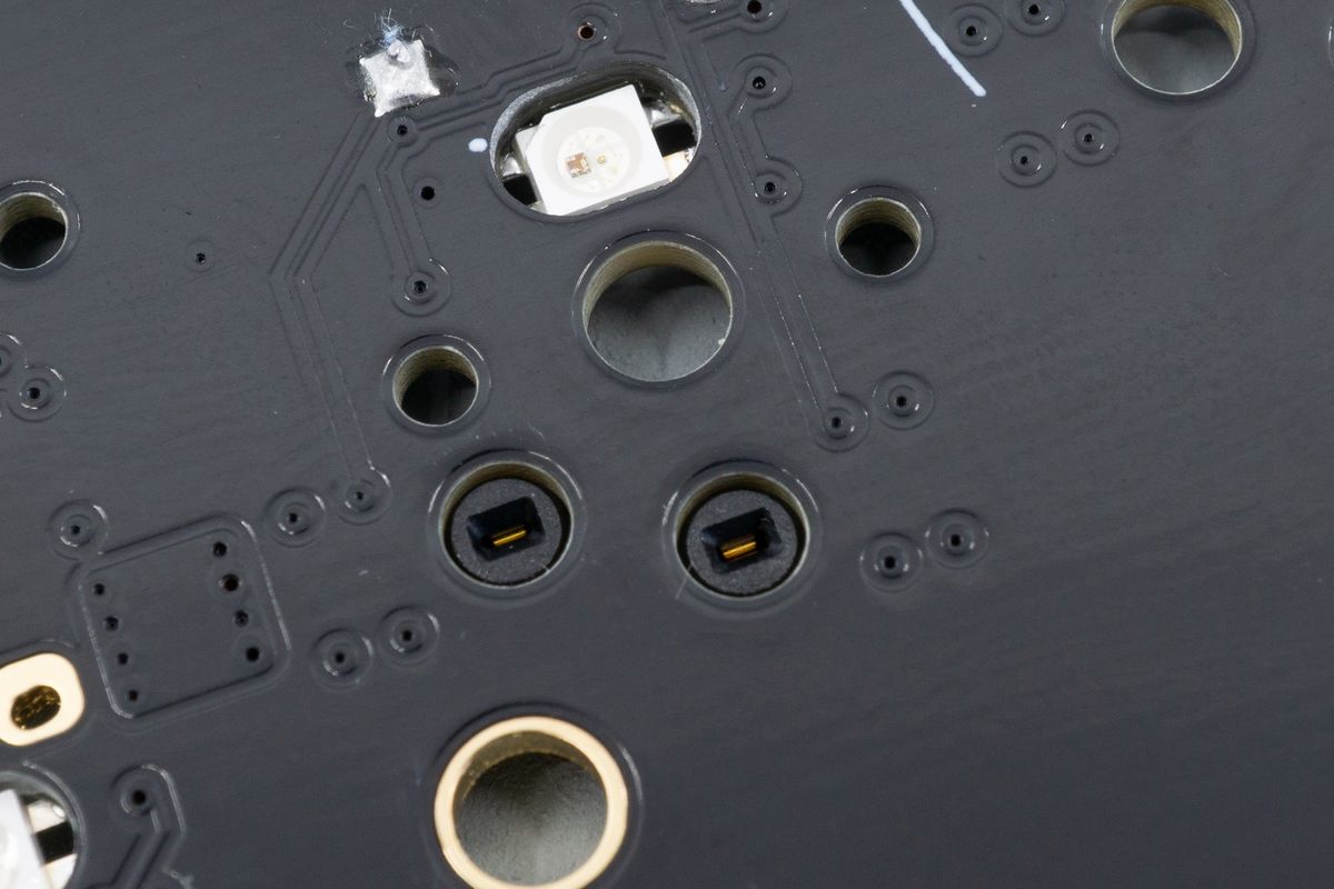
The footprint for a switch socket, with the big square pads.
Make sure that the socket is in the correct orientation. The hole for the switch should be unobscured.
The orientation does matter - make sure the flat side is facing toward you, and make sure the socket doesn't overlap with the big hole in the center. The socket in this picture is already soldered, you'll go do that too in the next few steps.
Now it’s time to solder the socket. Place the tip of the iron against both the pad and the leg, and feed solder into it until it forms a volcano-like shape. This should take about two to four seconds.
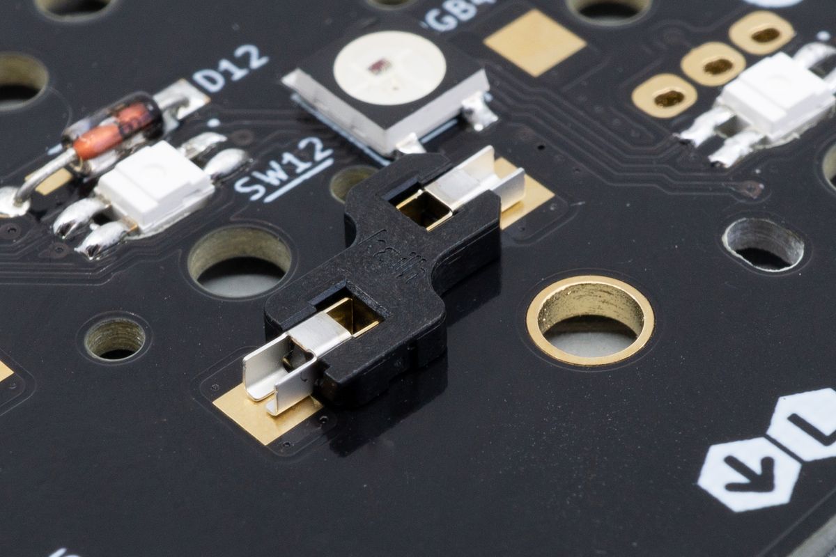
A switch soldered placed on top of the footprint. No soldering is done yet.
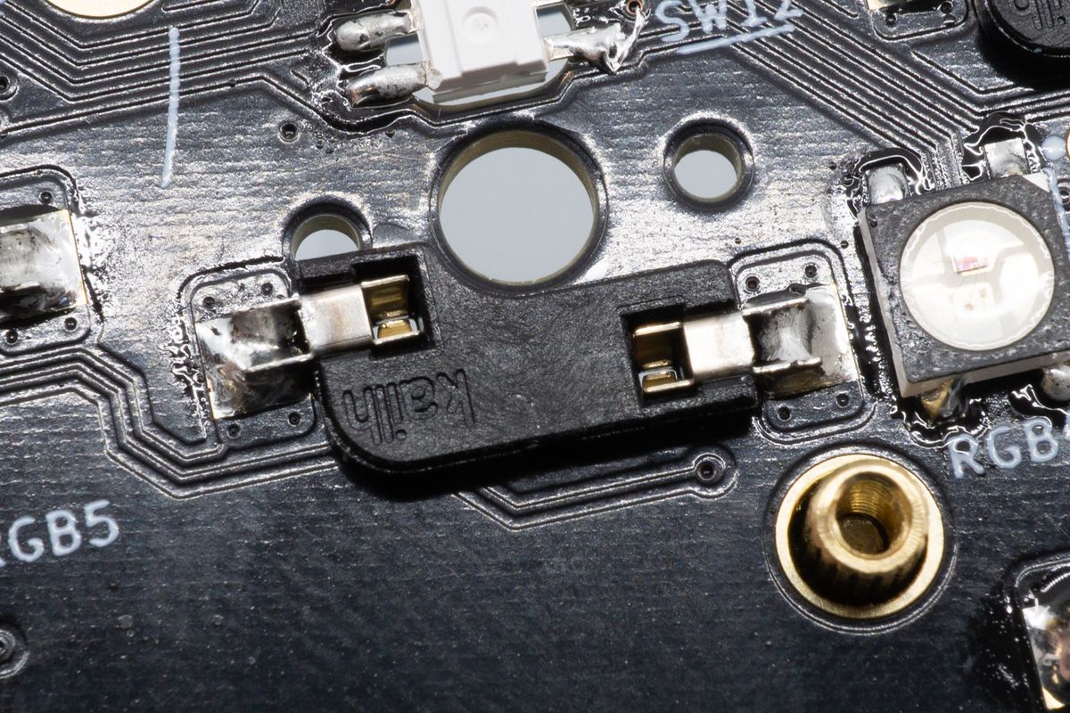
One of the legs is soldered. Notice that the entire pad is "filled" with solder, yet it's not a blob: it's a volcano-like shape.
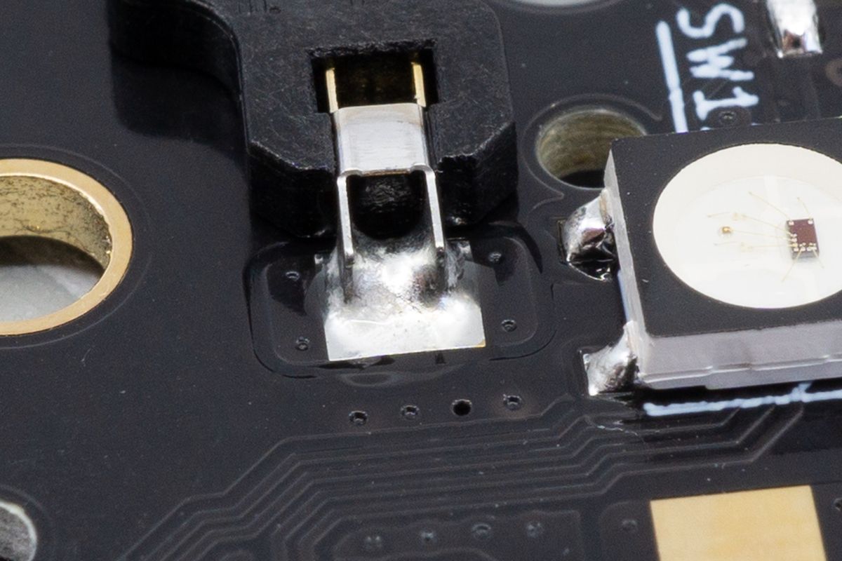
A close-up of the joint. On some sockets, the top side of the metal leg will be closed too, but you can still poke your soldering iron through it without having to bend the leg and without having to apply much force.
Check whether you like the alignment of the socket. It should sit flat on the bottom of the PCB, so there should be no gaps. If it needs adjustment, heat up the pad and use tweezers to push the socket down.
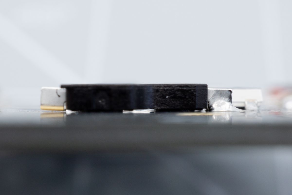
Side view of a switch socket with one leg soldered. Notice how it sits flush with the PCB along its entire body.
Then, solder the other pad, and continue doing this for all switch positions on the board.
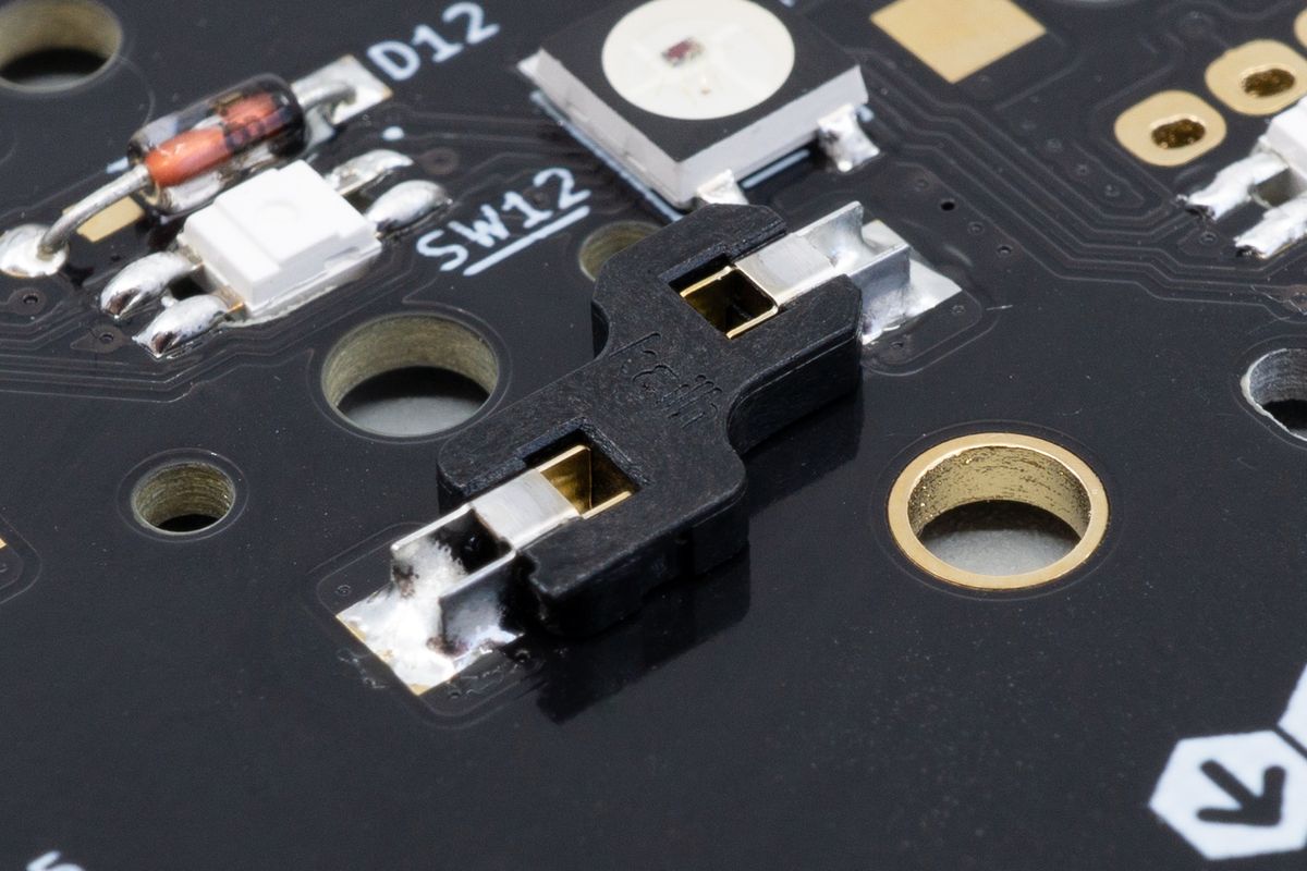
Both legs of the switch socket are now soldered.
Looking at the socket from the top side of the PCB, you'll see the contacts where the switch pins will connect.
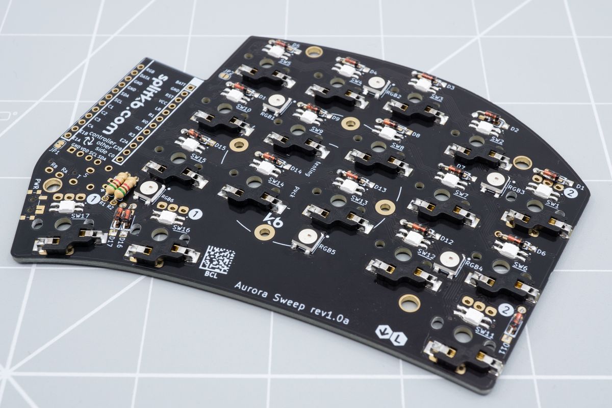
Back to the bottom side, with all the sockets soldered.
RGB underglow
Light shining down on your desk from the bottom of your keyboard. Learn how to solder RGB underglow LEDs.
Power switches
A power switch cuts off battery power when using a wireless controller.