

Display module
Setting the VIK voltage selector
For this module you won't need to touch the VIK voltage selector switch, it can be on either 5V or NC. The 5V is not connected on the module.
Installing the battery board
To install the battery board you will need the included 1.5 mm Allen key, screws, three 6 mm spacers, two 12 mm long hex screws, one 8 mm long hex screw and two small nuts. While the coin cell battery board is pictured here, the steps will be the same for the LiPo battery board.
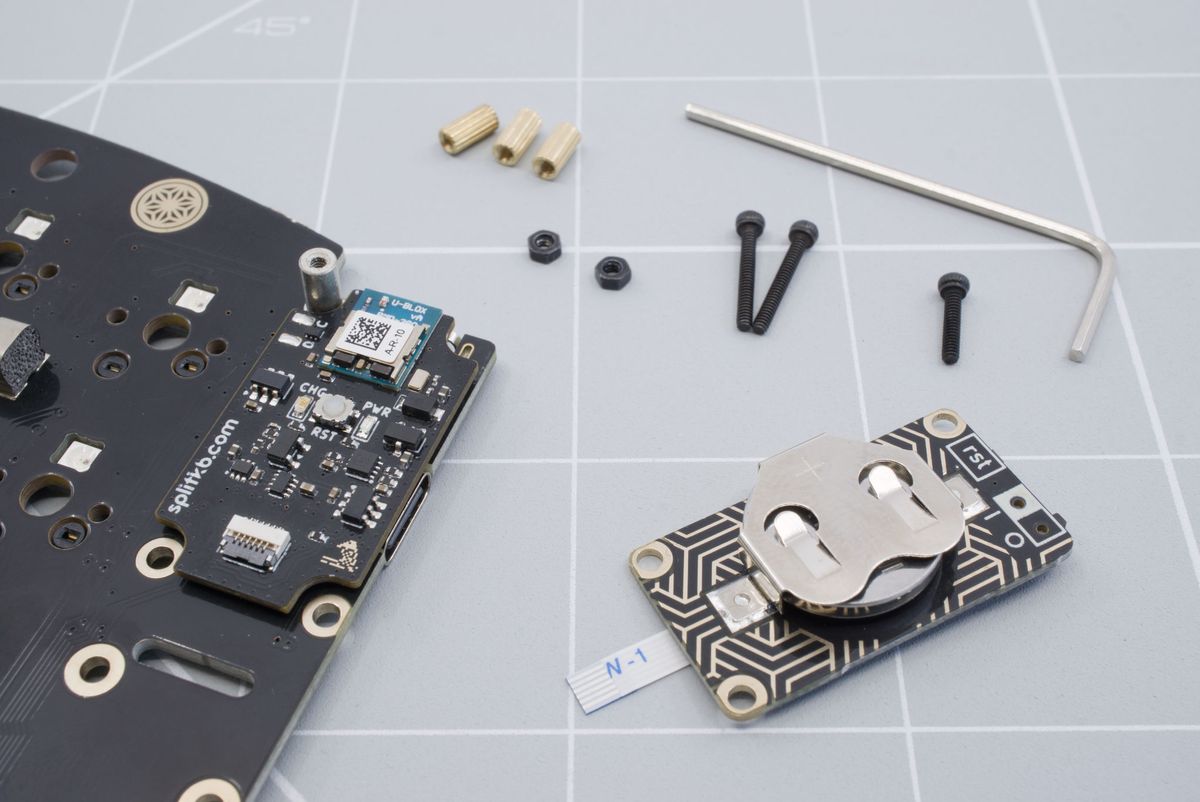
Required parts.
Start by lifting the gray little tab of the FFC connector on the controller with the non-conductive tool.
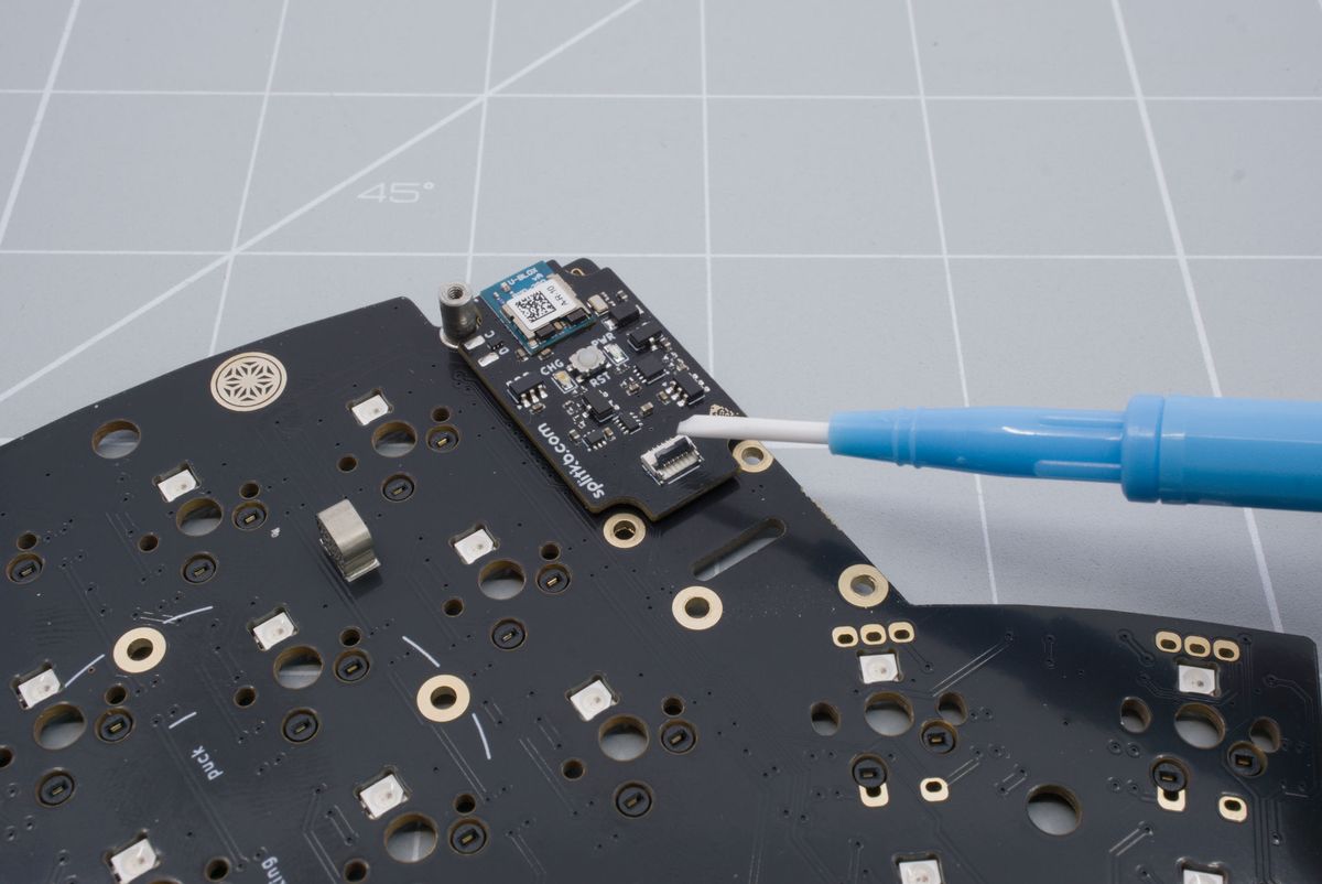
Lifting the tab on the controller.
Insert the flat cable with the blue part sticking up. Push the cable in as far as possible in to the connector.
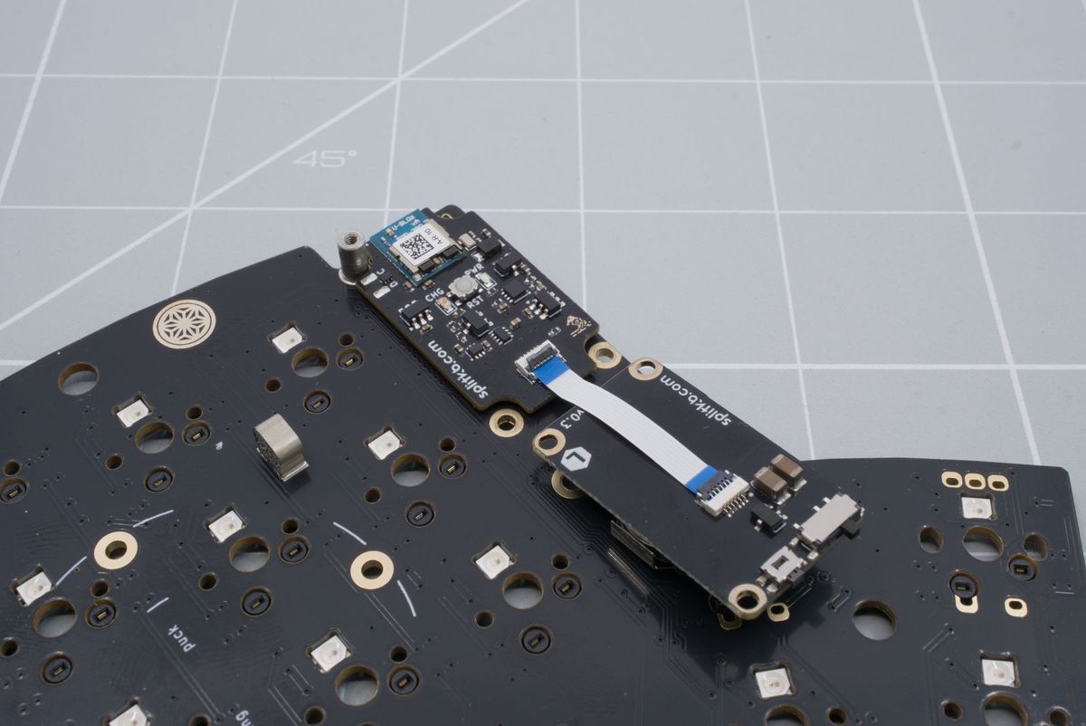
Inserting the flat cable.
Lower the tab back down with the non-conductive tool. You can lightly pull on the cable to see if it's in securely.
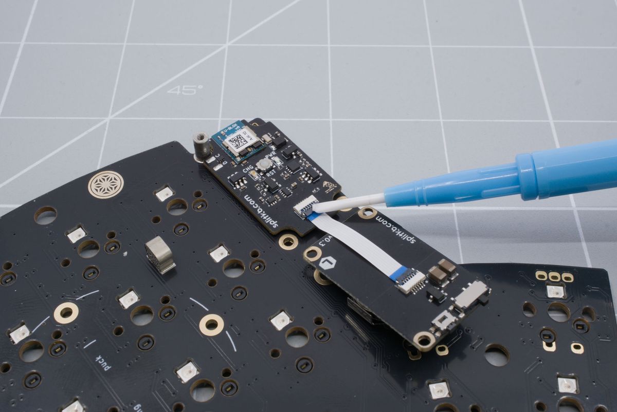
Lowering the tab back down.
Insert the 12 mm long hex screws through the bottom of the keyboard.
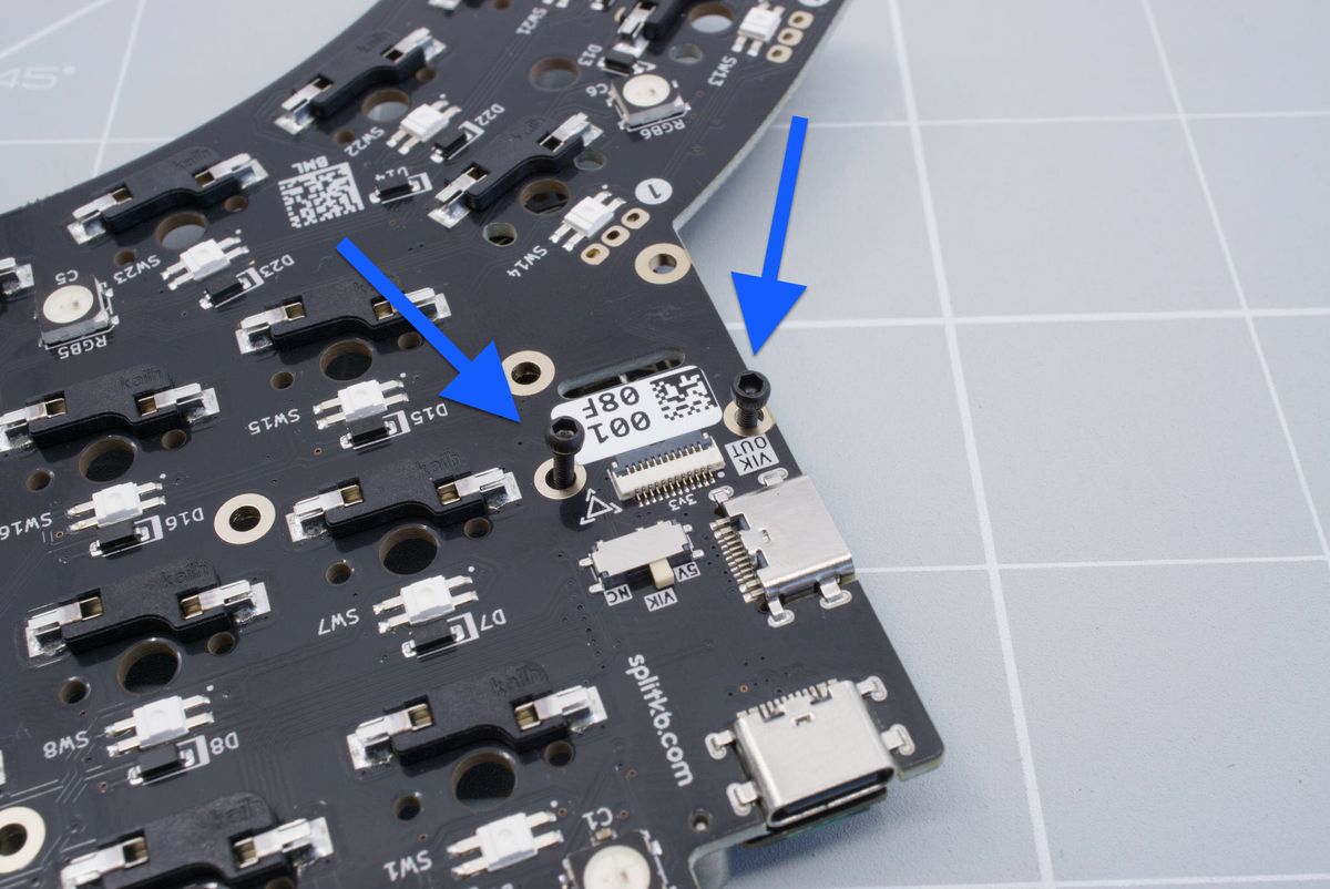
Inserting the hex screws.
Using a bit of tape, temporarily secure the screws.
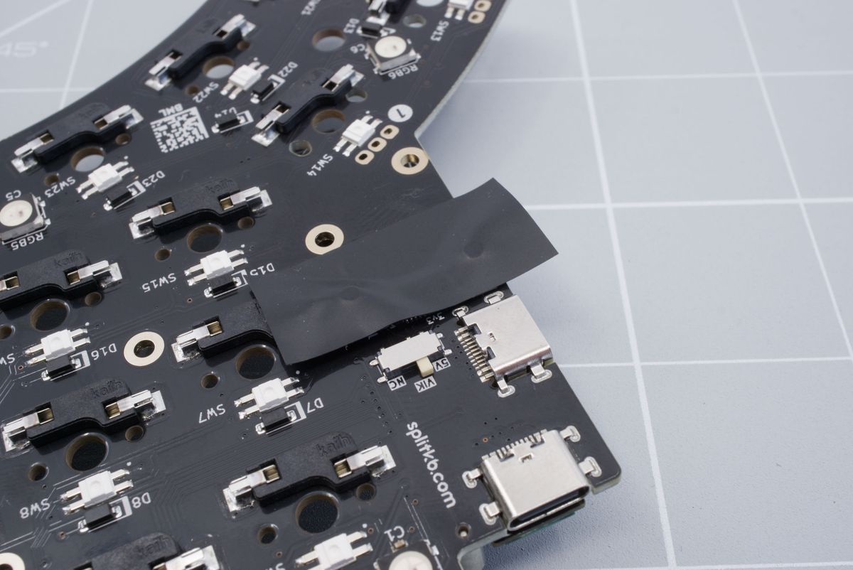
Adding tape to the bottom of the keyboard.
Add the 6 mm spacers on top.
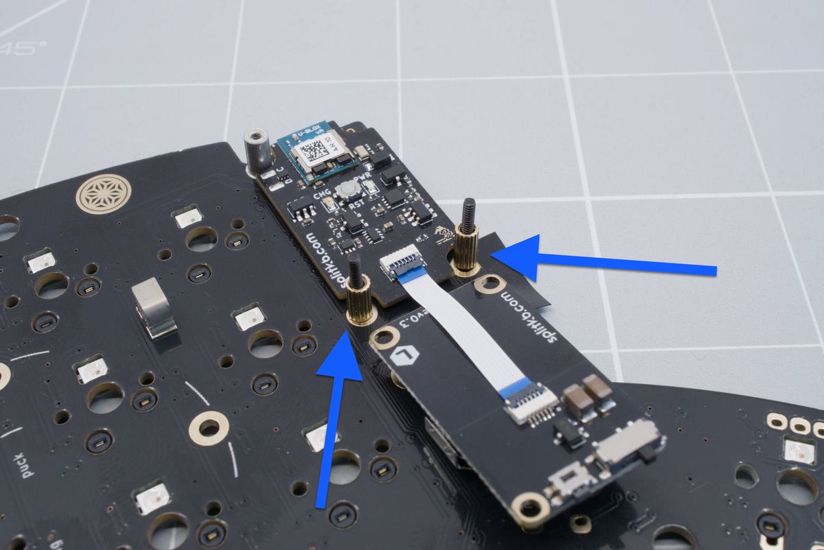
Adding the spacers.
Add the battery board on top.
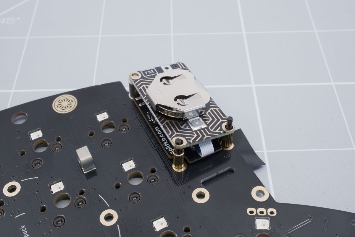
Installing the battery board.
Then add the small nuts to the top. Screw it in so that only a tiny part sticks out above the nut.
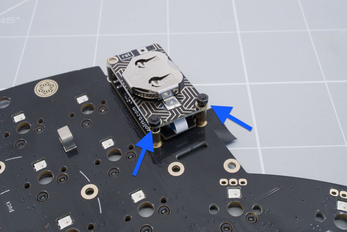
Securing the battery board.
The screw itself should only come out of the nut slightly as pictured below.
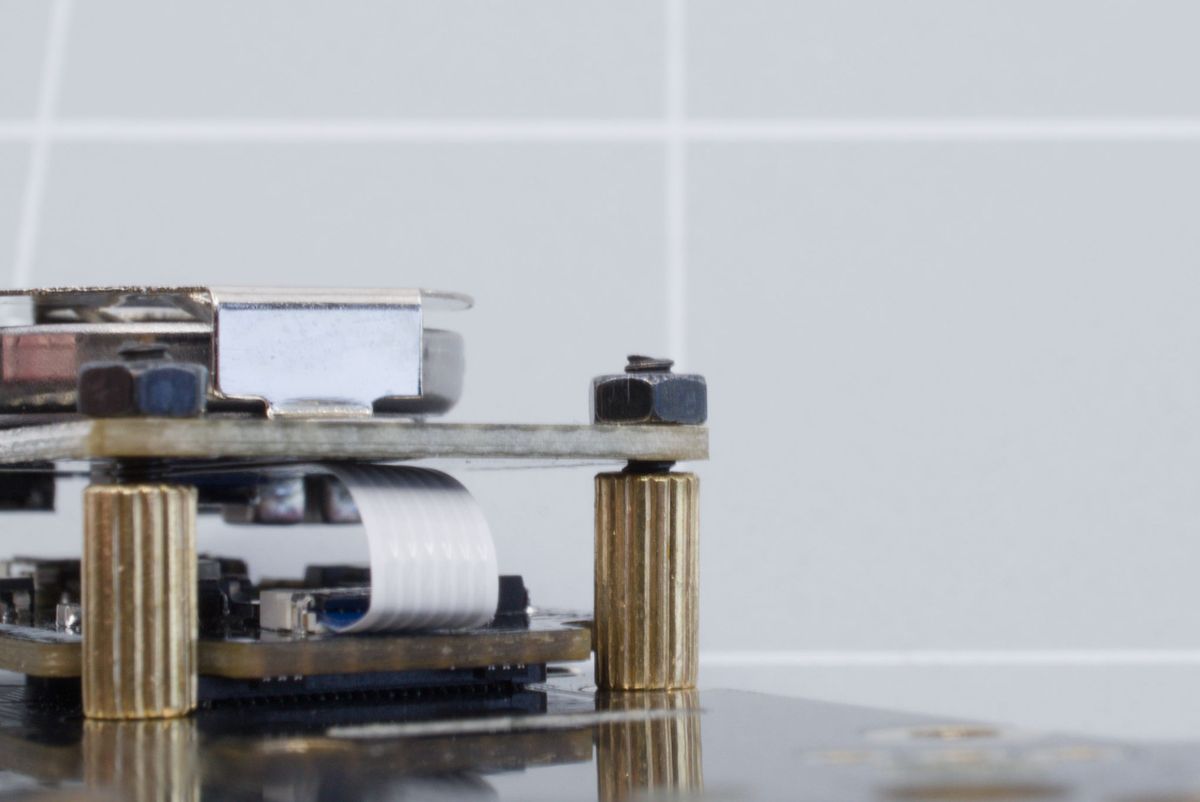
Bolt sticking above the nuts.
Now add a 6 mm spacer to the 8 mm long hex screw.
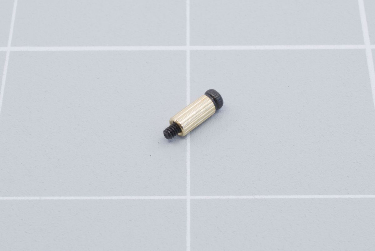
Preparing the top spacer.
Screw it in to the top hole of the battery board. You can tighten this fully, but make to keep the battery board straight. You can now also remove the tape on the bottom.
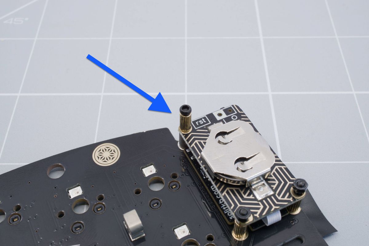
Tightening the top screw.
Installing the module
You will need your keyboard with the battery board prepared, the display module, the wide flat cable and the included 1.5 mm Allen key. You will also need the non-conductive tool to open and close the VIK connector.
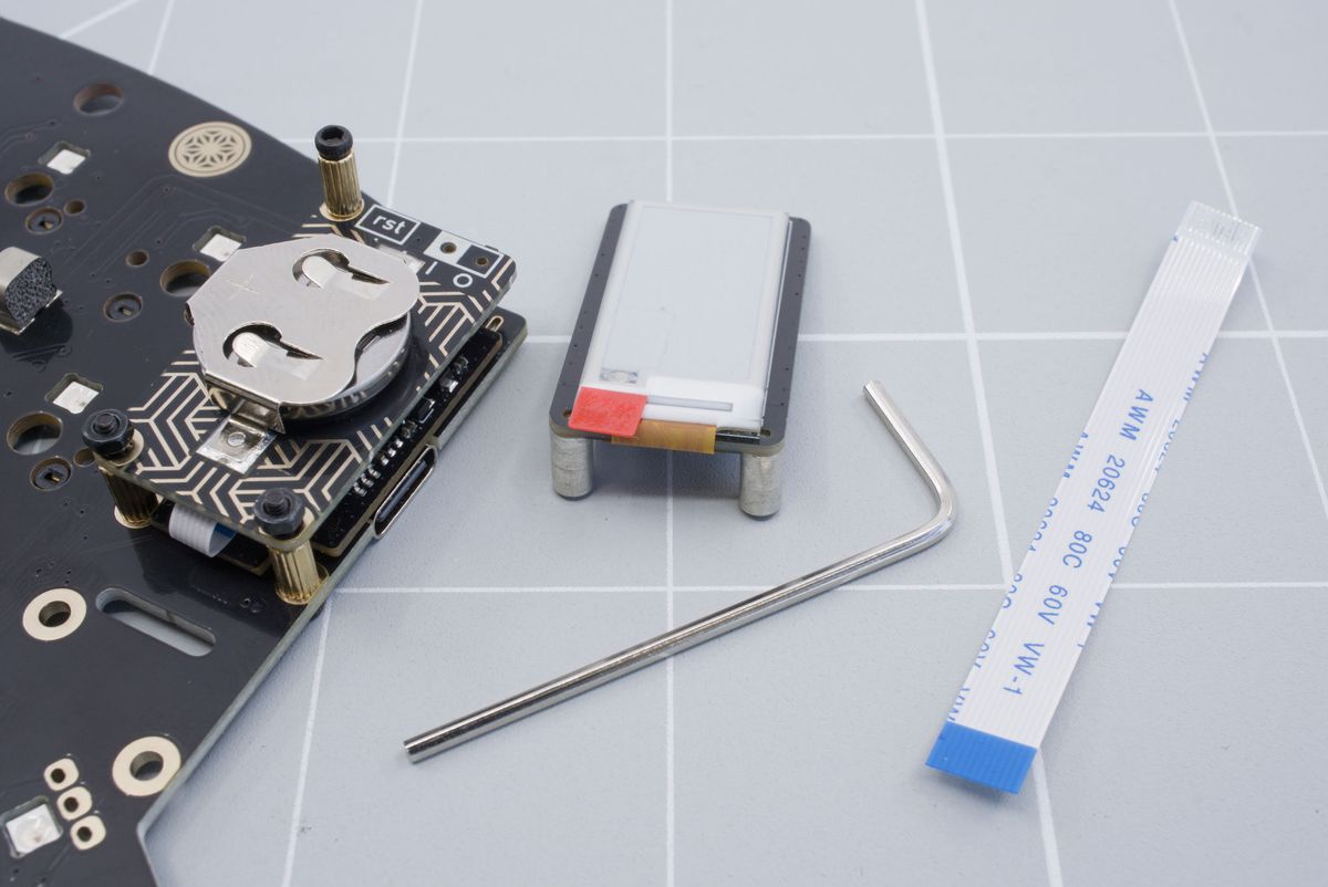
Required parts.
Start by lifting the gray little tab of the VIK connector on the module with the non-conductive tool.
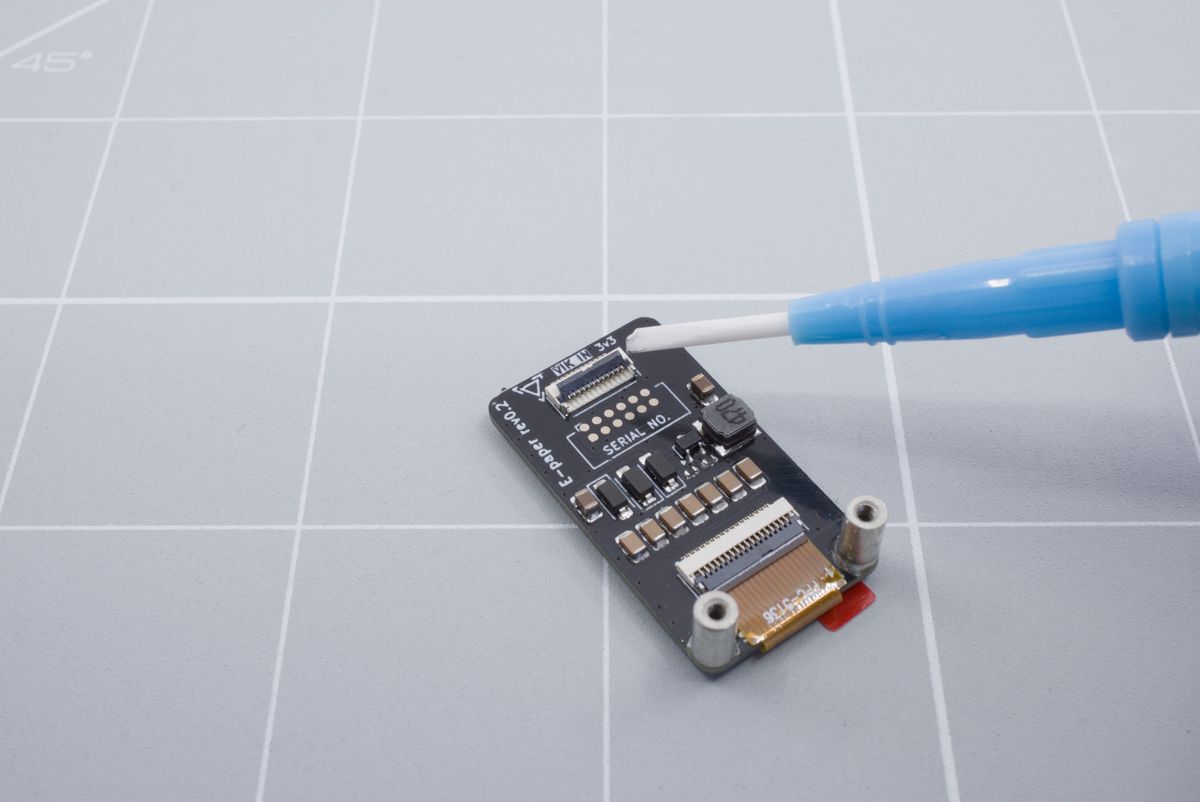
Lifting the tab on the module.
Insert the flat cable with the blue part sticking up. Push the cable in as far as possible in to the connector.
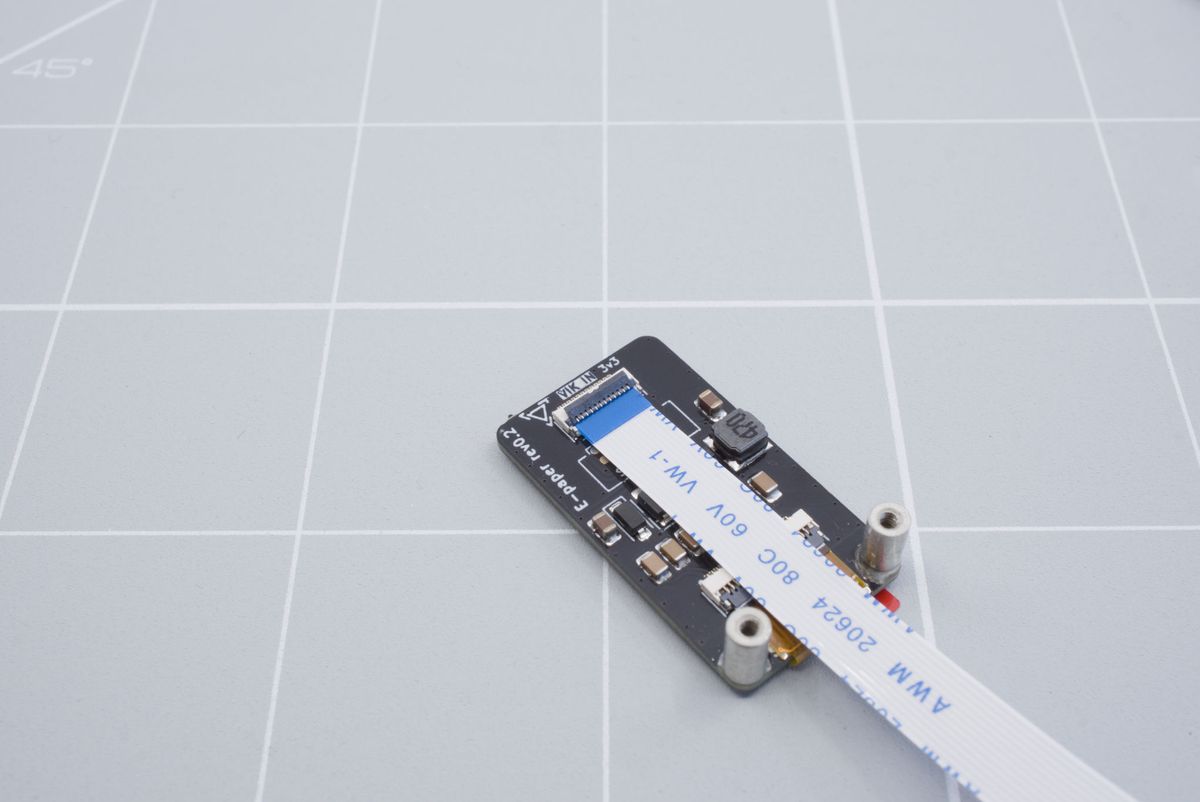
Inserting the flat cable.
Lower the tab back down with the non-conductive tool. You can lightly pull on the cable to see if it's in securely.
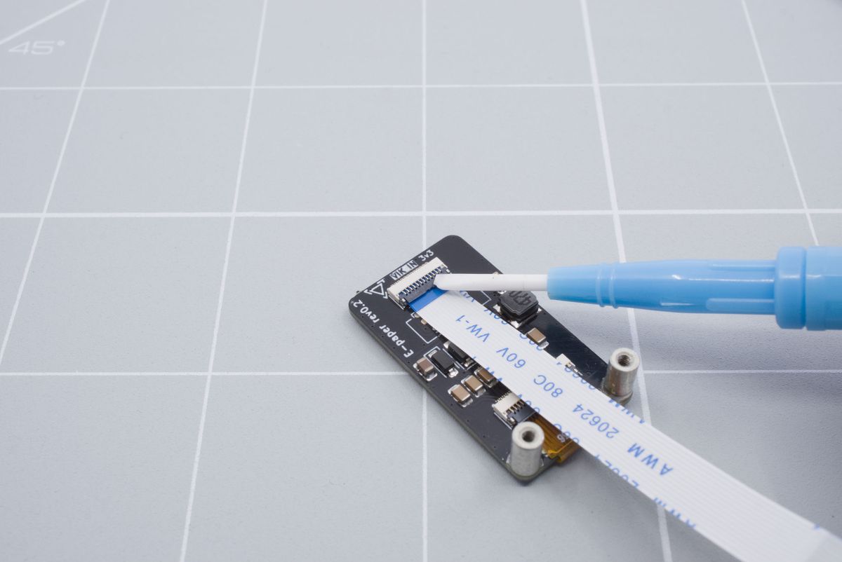
Lowering the tab back down.
Now position the module next to the keyboard.

Positioning the module.
Insert the cable through the hole in the keyboard and push it through all the way until the module lines up with the protruding screws.
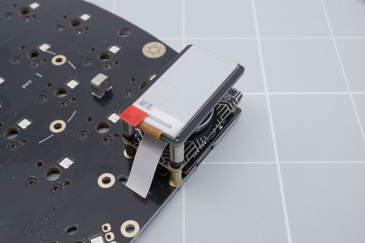
Module in the correct position.
Hold the nut in place while tightening the screw with the 1.5 mm Allen key. You can either hold the nut directly or apply pressure to the module at the points indicated by the arrows to prevent the nut from rotating. Repeat this for the other screw.
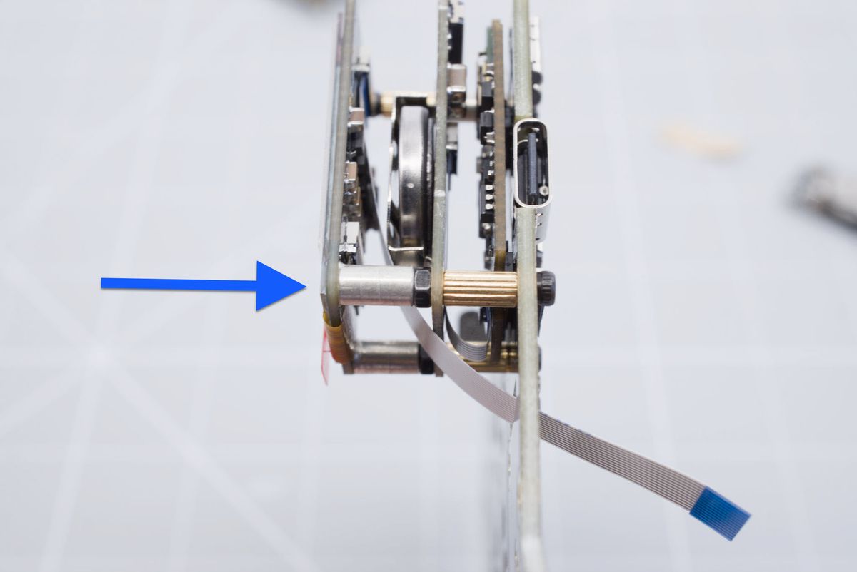
Where to put pressure when tightening the screws.
Now lift the tab up from the VIK connector on the keyboard using the non-conductive tool.
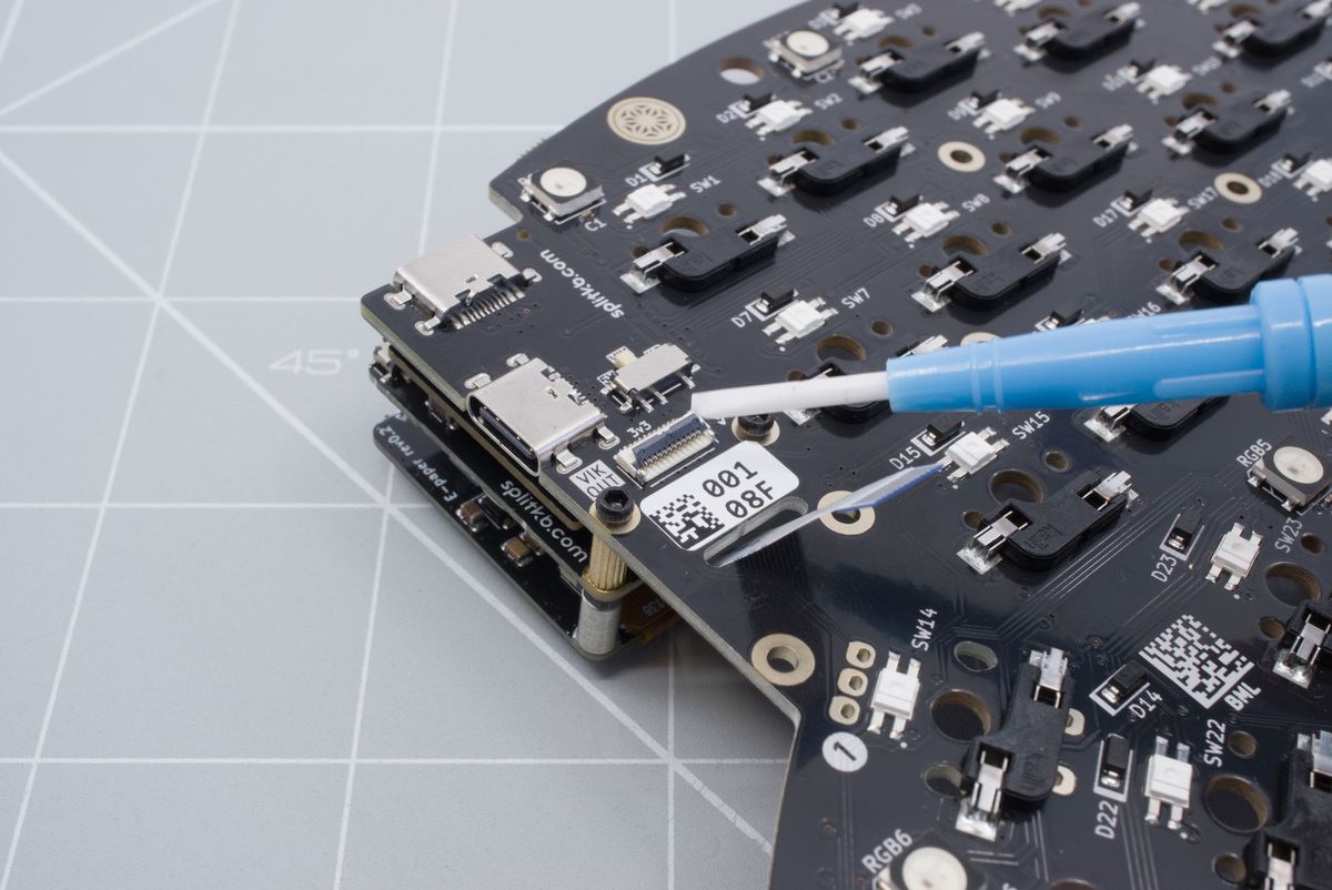
Lifting the tab up on the keyboard.
Insert the cable in to the keyboard.
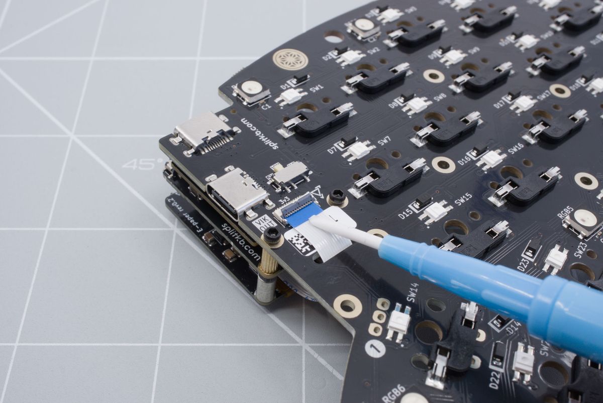
Pushing in the cable with a non-conductive tool.
Lower the tab back down with the non-conductive tool.
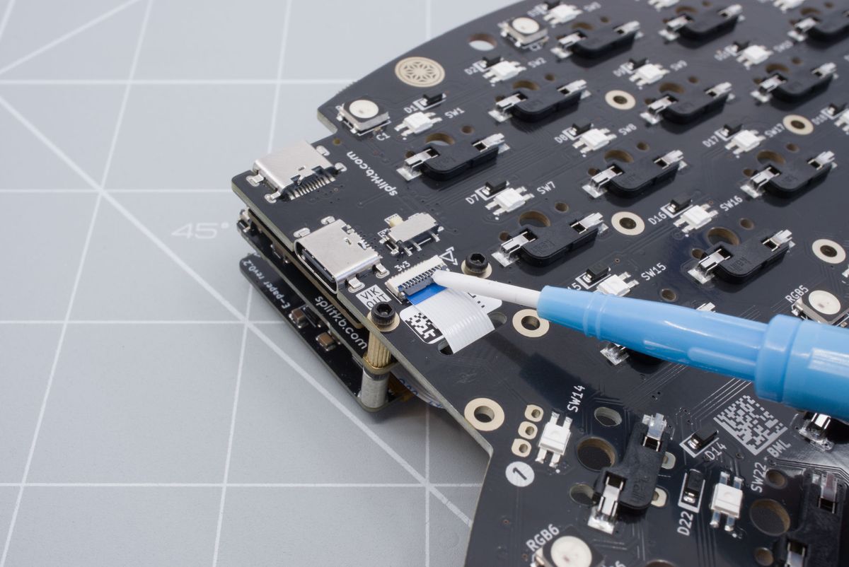
Lowering the tab back down.
You've now successfully installed the battery board and display module! You can now continue with the build guide.
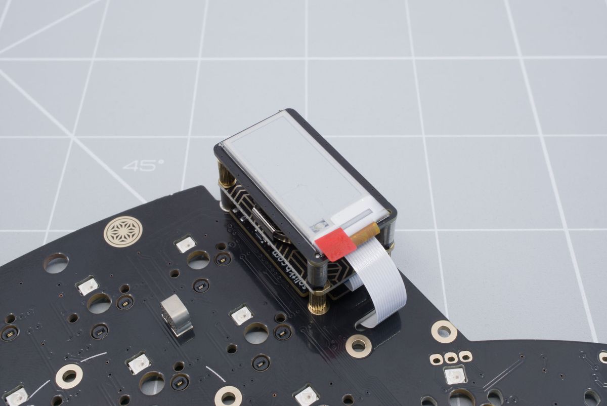
Installed module.
Modules
Installing and using Halcyon modules.
Encoder module
How to install and use the Encoder module with a battery board.