

Soldering the connector
The first step is to solder the connector board to your keyboard, either directly or using sockets.
Soldering directly to the keyboard (Recommended)
You will need the connector board, your keyboard PCB and a soldering iron
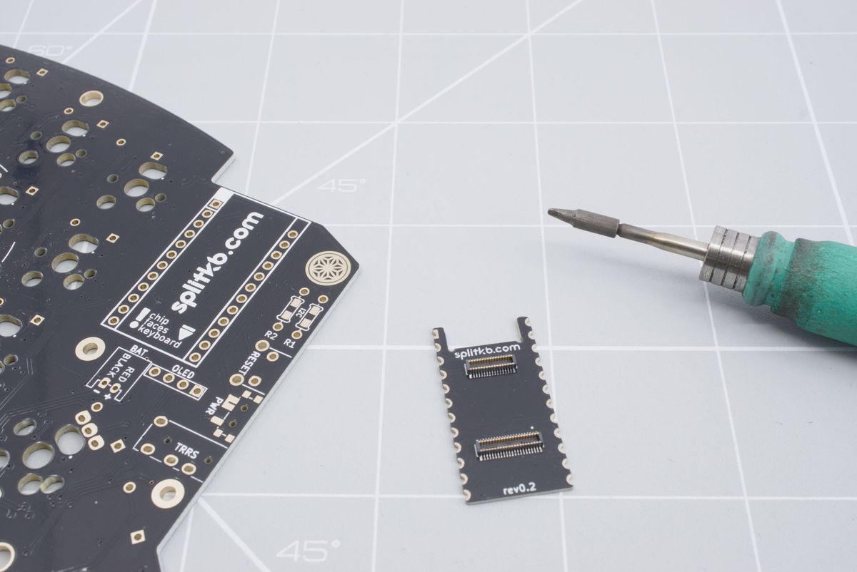
The connector board, keyboard PCB and soldering iron.
Align the connector board with the keyboard PCB. Make sure that the cutout is facing north.
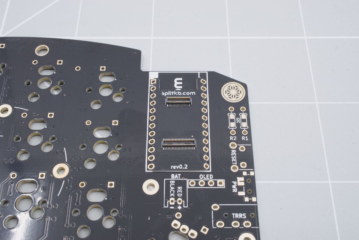
Aligning the connector board.
Solder the first corner to the keyboard. Make any adjustment needed to make sure the connector board is straight.
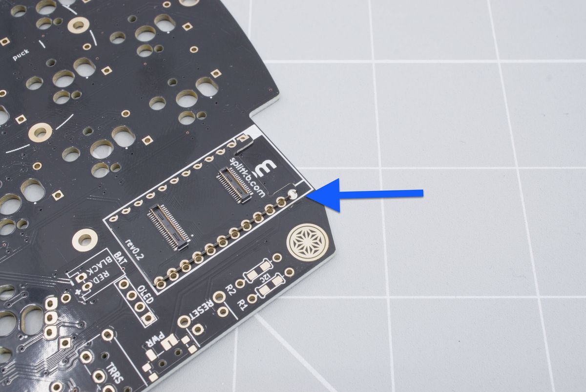
First pin soldered.
Start with the opposite edge, so the connector board will be locker in place.
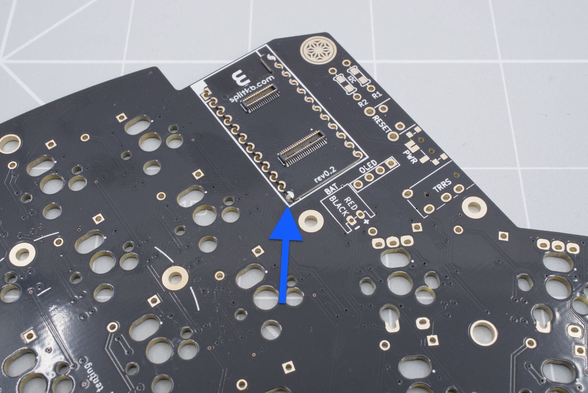
Second pin soldered.
Double check that the board is flat on the keyboard PCB.
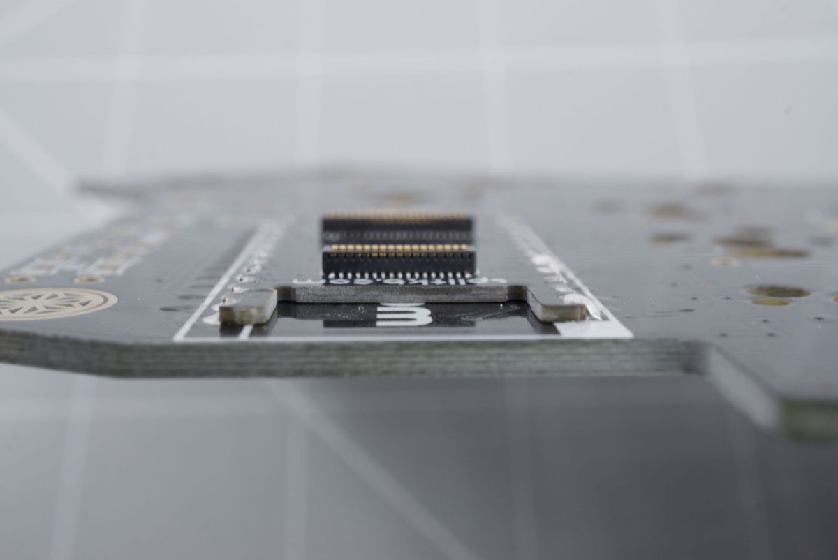
Connector board flat on the keyboard PCB.
Solder the rest of the pins. The easiest way to solder is to put your soldering iron almost inside the hole and add solder from the top
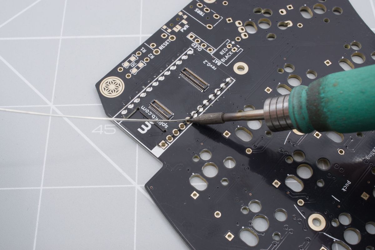
Soldering the connector board.
You've successfully soldered the connector board.
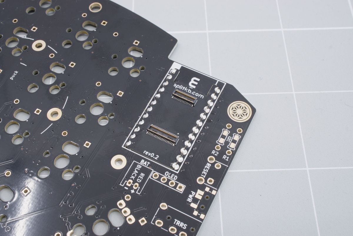
All pins soldered.
Using sockets
If you want to use sockets, to maybe install the battery under the microcontroller or if you want to replace an already installed microcontroller, you will have to modify the sockets slightly to accommodate for the screw used to attach the Halcyon modules.
You'll need your sockets and some pliers.
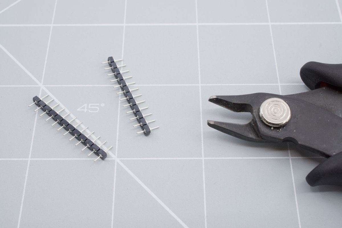
Sockets and some pliers.
Prepare the sockets by trimming the bottom two pins of both sockets.
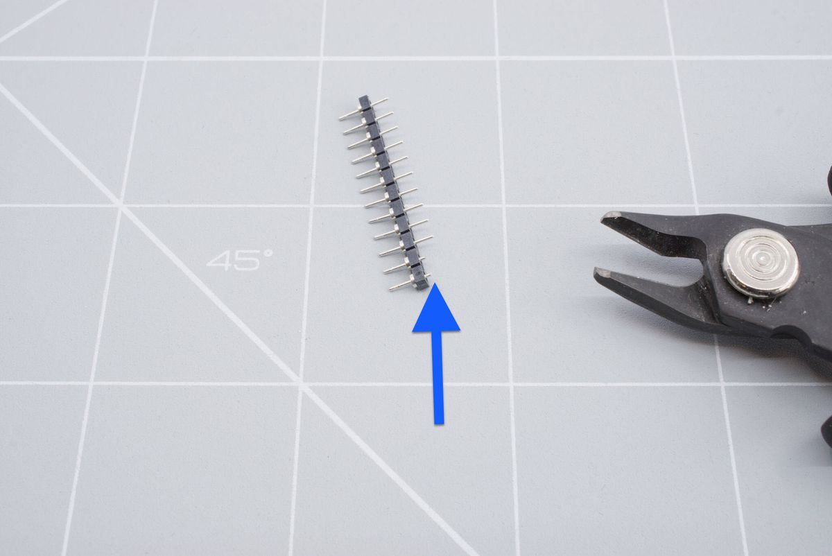
Trimmed sockets.
After that, please follow the guide from the Aurora build guide. Where the trimmed socket pins are facing south.
Aurora build guide sockets pageAfter soldering you want snip of the heads of the headers, this doesn't have to be all the way flush
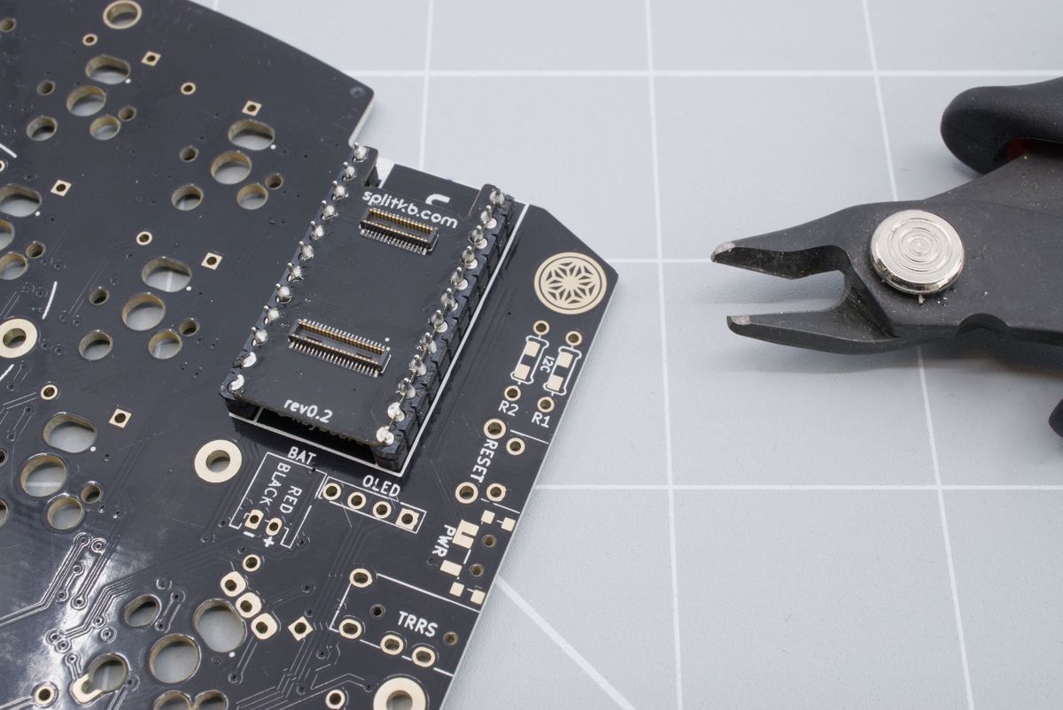
Trimming headers.
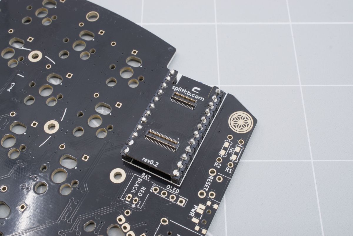
Trimmed headers.
The bottom two pins on both side should be flush with the connector board. No solder should stick out.
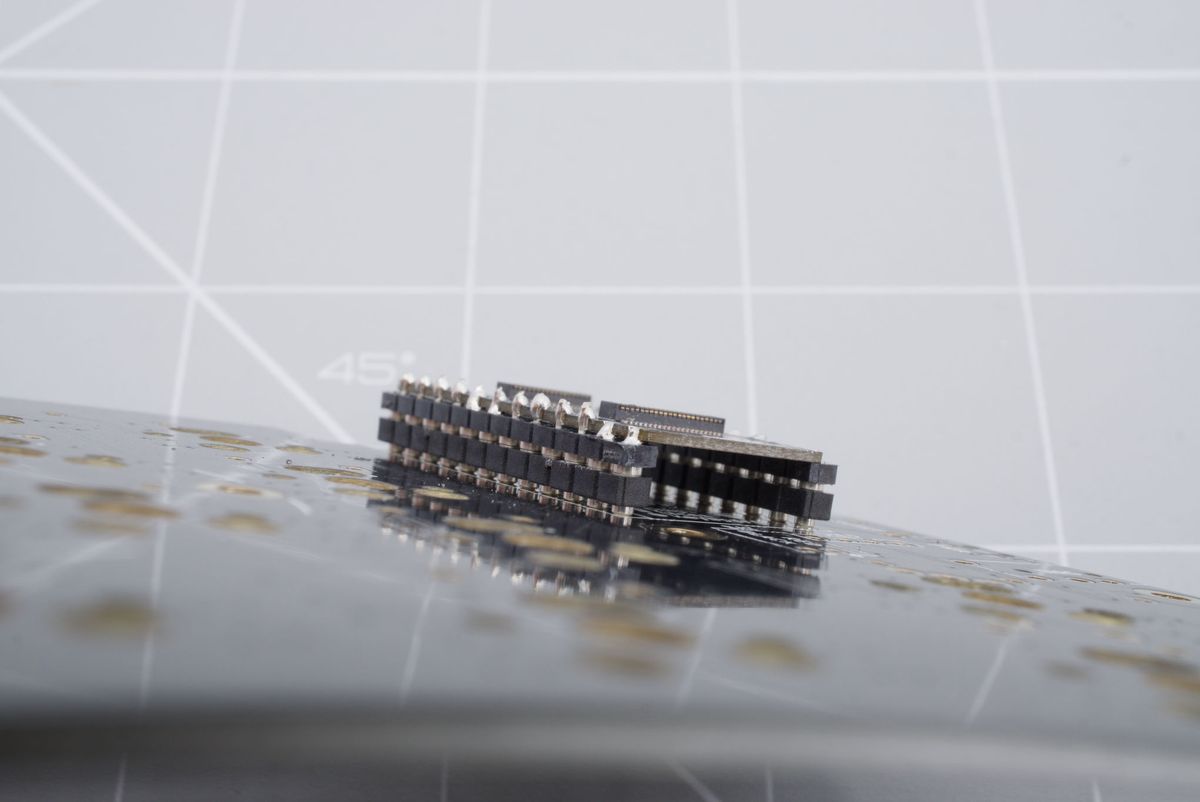
Flush pins of the connector board.
About
The Halcyon Pro Micro adapter
Installing the adapter and modules
Solderering the Halcyon to Pro Micro connector to your Pro Micro-based keyboard.